Gas recovering apparatus, vacuum exhausting method, and vacuum exhausting apparatus
Inactive Publication Date: 2003-08-14
OHMI TADAHIRO +1
View PDF6 Cites 0 Cited by
Summary
Abstract
Description
Claims
Application Information
AI Technical Summary
This helps you quickly interpret patents by identifying the three key elements:
Problems solved by technology
Method used
Benefits of technology
Benefits of technology
[0009] The present invention has as an object thereof the cooling, liquefaction, recovery and reuse of exhaust gas components in manufacturing processes, and to make it possible to use toxic or useful gases without the necessity of disposal. Furthermore, the present invention has as object thereof to drastically reduce the frequency of the maintenance of exhaust systems by combining this recovery method with a vacuum exhaust system.
[0011] Furthermore, the present inventors have discovered that the reverse dispersion of the exhaust gases can be suppressed by causing the flow of an appropriate amount of gas from appropriate positions in the exhaust line. In other words, the present invention comprises a vacuum exhaust method comprising a mechanism for introducing gas, a vacuum exhaust apparatus for exhausting gas and a chamber for storing a vacuum, wherein the interior of the chamber is constantly subjected to the flow of some type of gas; the present invention also comprises a vacuum exhaust apparatus in which the mechanism for introducing gas is provided between the vacuum exhaust pump and the chamber.
[0013] Furthermore, by means of the vacuum exhausting method and apparatus of the present invention, it is possible to suppress the revers diffusion of the exhaust gas components within the pump.
Problems solved by technology
In various processes which employ special material gases, a problem arises in that, among the exhaust gas components, exhaust gas components such as radicals or the like which remain unreacted or incompletely reacted are deposited on the surfaces of the exhaust line, and presently, regular maintenance is required.
However, in these two methods, it is also necessary to treat the solution, and furthermore, once combustion has occurred, it is impossible to reuse the resources.
In dry removal apparatuses, using an adsorbing material, harmful gases are absorbed and removed.
Furthermore, it is not merely the case that recovery methods have not been established; there is also a problem in that, even in vacuum exhaust methods, the exhaust gases diffuse back within the pump, and return again to the processing spaces.
Method used
Image
Click on the blue label to locate the original text in one second.
Reading with bidirectional positioning of images and text.
Examples
embodiment example 1
[0043] (Embodiment Example 1)
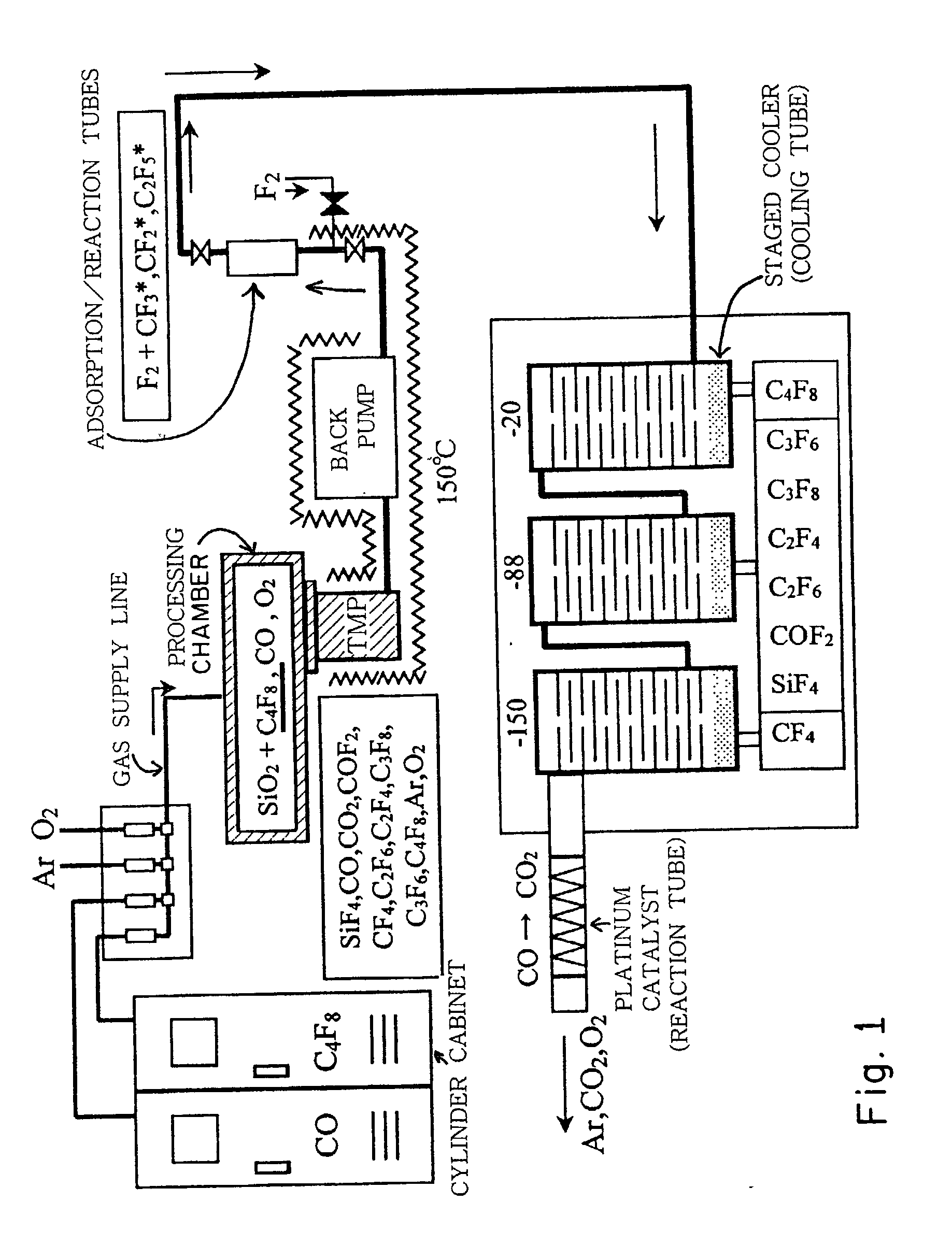
[0044] FIG. 1 shows an embodiment example of the present invention when exhaust gases from a siliconwaferetching process are to be liquefied and recovered.
[0045] In the present embodiment, under a flow of CO, Ar, O.sub.2, C.sub.4F.sub.8, and in a state in which a constant pressure is maintained by evacuation using a vacuum pump, the gases are excited by a plasma, and the etching of a siliconwafer is conducted.
[0046] The excited gases remain in the plasma state, so that they are deposited at spots having low temperatures. For this reason, after the reaction gases are used in a gaseous state, they are liquefied and recovered.
[0048] The conditions of the etching process are as follows: a standard DRAM device is used, and the gas flow rates are CO: 100 cc / min, AR: 300 cc / min, O.sub.2: 50 cc / min, and C.sub...
embodiment example 2
[0060] (Embodiment Example 2)
[0061] In FIG. 4, an embodiment example of the present invention is shown in which exhaust gases from an Si-Epi (epitaxial) growth process are liquefied and recovered.
[0062] The present process is conducted using SiHCl.sub.3 and H.sub.2. In the present process, plasma is not employed, and the reaction is conducted by heating to a high temperature, so that the reaction is not complete, and unreacted components are deposited on the interior of the reaction vessel and on the exhaust system. For this reason, after the reaction gas is reacted as a gas, liquefaction and recovery are conducted.
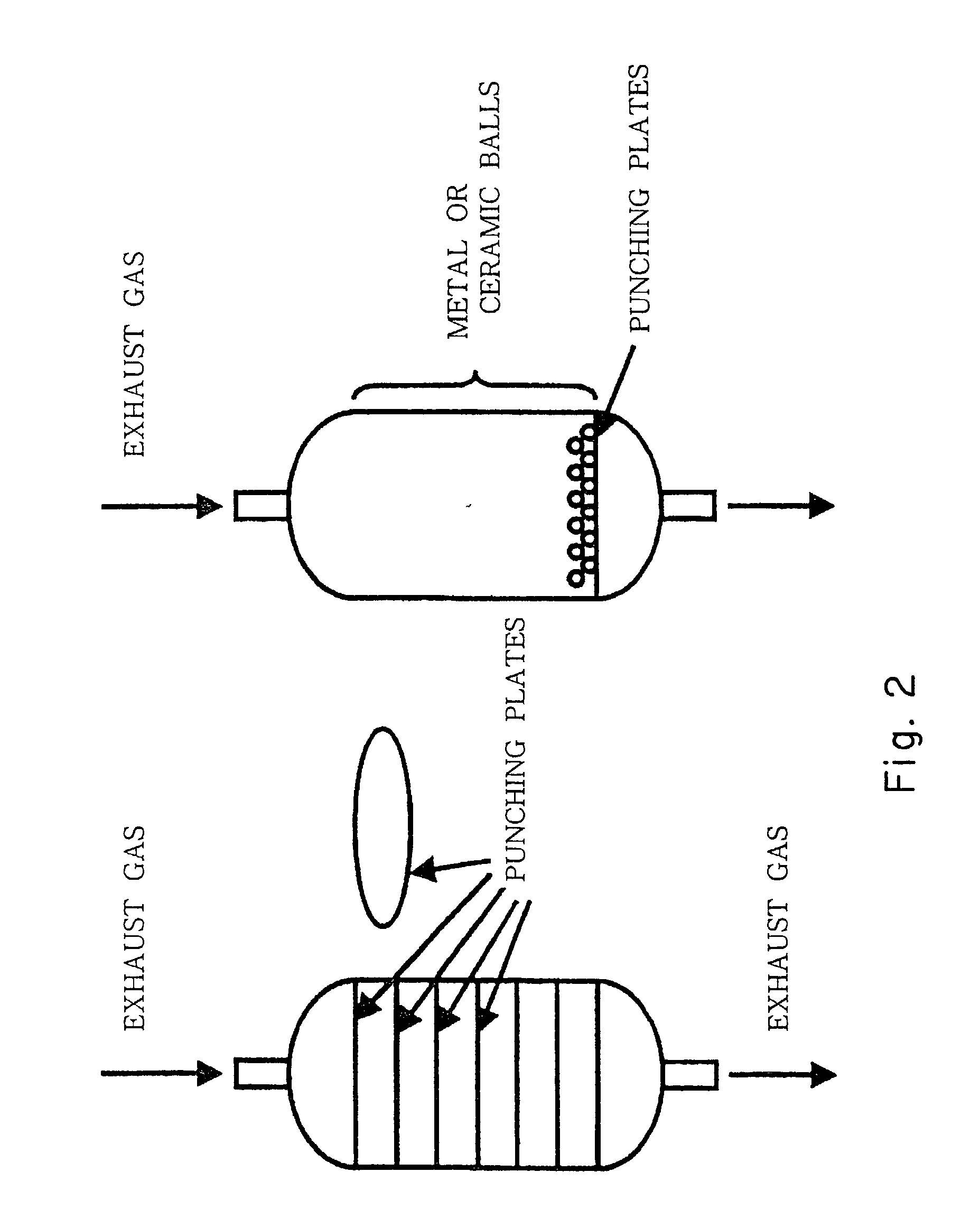
[0063] As shown in FIG. 2, the system comprises a vacuum pump, adsorption and reaction tubes, cooling tubes, and a combustion type removal apparatus.
[0064] The process comprises H.sub.2 annealing and film formation; cleaning is conducted using HCl between processes.
[0065] In actual film formation processes, H.sub.2 is used as a carrier gas and is caused to flow at a rate ...
PUM
Property
Measurement
Unit
Angle
aaaaa
aaaaa
Temperature
aaaaa
aaaaa
Pressure
aaaaa
aaaaa
Abstract
The present invention has an object thereof to make possible the recycling of exhaust gas components in a manufacturing process by cooling, liquefaction, and recovery, and to use toxic or useful gases without disposal, and to dramatically reduce the frequency of exhaust system maintenance by combining such a recovery method with a vacuum exhaust system. In the gas recovering apparatus, followings are disposed downstream from the chamber in an exhaust line; adsorption columns for adsorbing one or more exhaust gas components within a exhaust gas from a chamber, or reaction tubes for directly degrading such components, a means for introducing gas which is able to react to said exhaust gas components upstream from said adsorption tubes or reaction tubes, and cooling tubes for liquefying and recovering exhaust gases from said adsorption tubes or reaction tubes. Furthermore, the present invention also relates to a vacuum exhausting method in which, in the vacuum apparatus, some type of gas is continuously caused to flow within the chamber, and relates to a vacuum exhausting apparatus, in which a mechanism is provided for introducing gas between the vacuum exhausting pump and the chamber.
Description
BACKGROUND OF THE INVENTION AND DESCRIPTION OF RELATED ART[0001] 1. Field of the Invention[0002] The present invention relates to an apparatus for the recovery and reuse of exhaust gases in manufacturing processes using special material gases, and relates to a vacuum exhausting apparatus and method for conducting manufacturing processes in ultraclean atmospheres.[0003] 2. Background Art[0004] In various processes which employ special material gases, a problem arises in that, among the exhaust gas components, exhaust gas components such as radicals or the like which remain unreacted or incompletely reacted are deposited on the surfaces of the exhaust line, and presently, regular maintenance is required.[0005] Among the methods conventionally employed in exhaust gas processing apparatuses, removal apparatuses exist which employ dry methods, wet methods, and combustion methods.[0006] In combustion type removal apparatuses, removal is conducted by the combustion of combustible gases, an...
Claims
Application Information
Patent Timeline
Application Date:The date an application was filed.
Publication Date:The date a patent or application was officially published.
First Publication Date:The earliest publication date of a patent with the same application number.
Issue Date:Publication date of the patent grant document.
PCT Entry Date:The Entry date of PCT National Phase.
Estimated Expiry Date:The statutory expiry date of a patent right according to the Patent Law, and it is the longest term of protection that the patent right can achieve without the termination of the patent right due to other reasons(Term extension factor has been taken into account ).
Invalid Date:Actual expiry date is based on effective date or publication date of legal transaction data of invalid patent.

