
Piezoelectric device, piezoelectric actuator, liquid ejecting head, and liquid ejecting apparatus

Active Publication Date: 2011-05-12
SEIKO EPSON CORP
View PDF8 Cites 23 Cited by
  • Summary
  • Abstract
  • Description
  • Claims
  • Application Information

AI Technical Summary

Benefits of technology

[0018]In the piezoelectric device having such an advantage, a material of the first conductive layer of the first electrode is one metal selected from the group consisting of Ti, Zr, Hf, V, Nb, Ta, Cr, Mo, W, Mn, Fe, Co, Ni, Cu, Ag, and Au or is an alloy containing at least two metals selected from such group. Accordingly, in the piezoelectric device having such an advantage, the first conductive layer of the first electrode does not contain the noble metals (Ru, Rh, Pd, Os, Ir, and Pt). Consequently, in addition to the advantageous effects according to the first aspect, another advantageous effect is provided, in which the first conductive layer has at least any one of high conductivity and high durability.
[0019]It is preferable that the first intermediate layer contains a nitrogen compound containing at least one metal selected from the group consisting of Ti, Al, Ta, W, and Si.
[0020]In the piezoelectric device having such a configuration, the first intermediate layer effectively suppresses the diffusion of moisture and oxygen from a side of the piezoelectric layer to the first conductive layer. Accordingly, the diffusion of the moisture and oxygen from the side of the piezoelectric layer to the first conductive layer is sufficiently suppressed, for example, during the sintering of the piezoelectric layer in the manufacturing of the piezoelectric device. Consequently, in addition to the above advantageous effects, the piezoelectric device having such a configuration has another advantageous effect in which a material of the first conductive layer is processed in good conditions.
[0021]It is preferable that the second conductive layer contains a conductive oxide containing at least one element selected from the group consisting of La, Sr, Ca, In, Ni, Ru, and Sn.
[0022]In the piezoelectric device having such a configuration, a material of the second conductive layer of the first electrode is an oxide containing at least one element selected from the group consisting of La, Sr, Ca, In, Ni, Ru, and Sn. Accordingly, in addition to the above advantageous effects, another advantageous effect is provided, in which the piezoelectric device having such a configuration has at least any one of both an improvement in electrical conductivity of the second conductive layer and an improvement in crystalline properties of the piezoelectric layer.
[0023]According to a second aspect of the invention, there is provided a piezoelectric actuator including: the piezoelectric device having any one of the above advantages; a third intermediate layer provided so as to be in contact with the first conductive layer; and a substrate provided so as to be in contact with the third intermediate layer. The substrate deforms in response to the deformation of the piezoelectric device.

Problems solved by technology

Such metals have advantages such as relatively high electrical conductivity and chemical stability but have a disadvantage such as relatively high rigidity, resulting in such metals being fragile.
Accordingly, in existing piezoelectric devices, because the electrode of the piezoelectric device contains such platinum group metals, the rigidity of the electrode may be increased to restrict the change in the shape of the piezoelectric device, or the friability of the electrode may cause destruction of the electrode and piezoelectric layer.
Furthermore, such metals are expensive nowadays, resulting in high production costs of piezoelectric devices.

Method used


Image

  • Piezoelectric device, piezoelectric actuator, liquid ejecting head, and liquid ejecting apparatus
  • Piezoelectric device, piezoelectric actuator, liquid ejecting head, and liquid ejecting apparatus
  • Piezoelectric device, piezoelectric actuator, liquid ejecting head, and liquid ejecting apparatus

Examples


Embodiment Construction

[0041]Preferred embodiments of the invention will be described with reference to the accompanying drawings. The embodiments to be described are examples of the invention. The embodiments of the invention are not limited to the embodiments described below and include various modifications without departing from the scope of the invention.

1. Piezoelectric Device

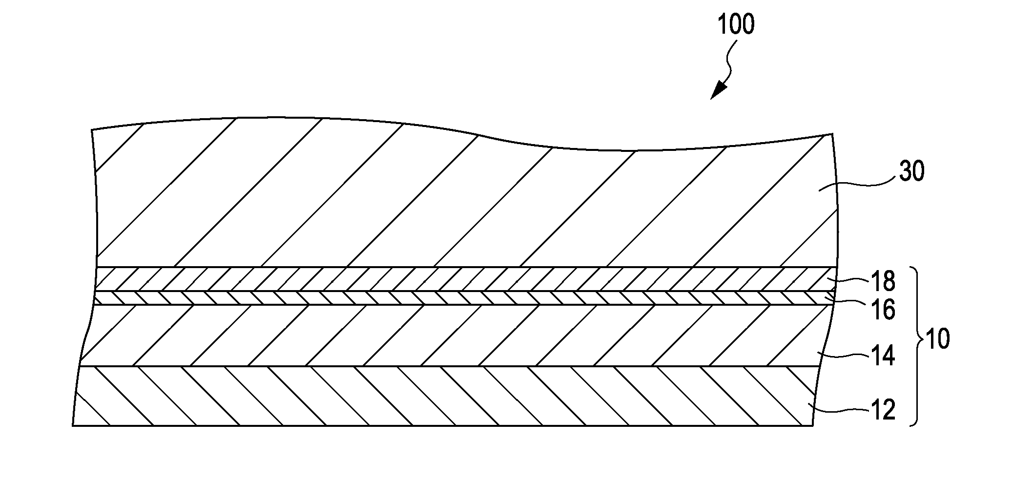
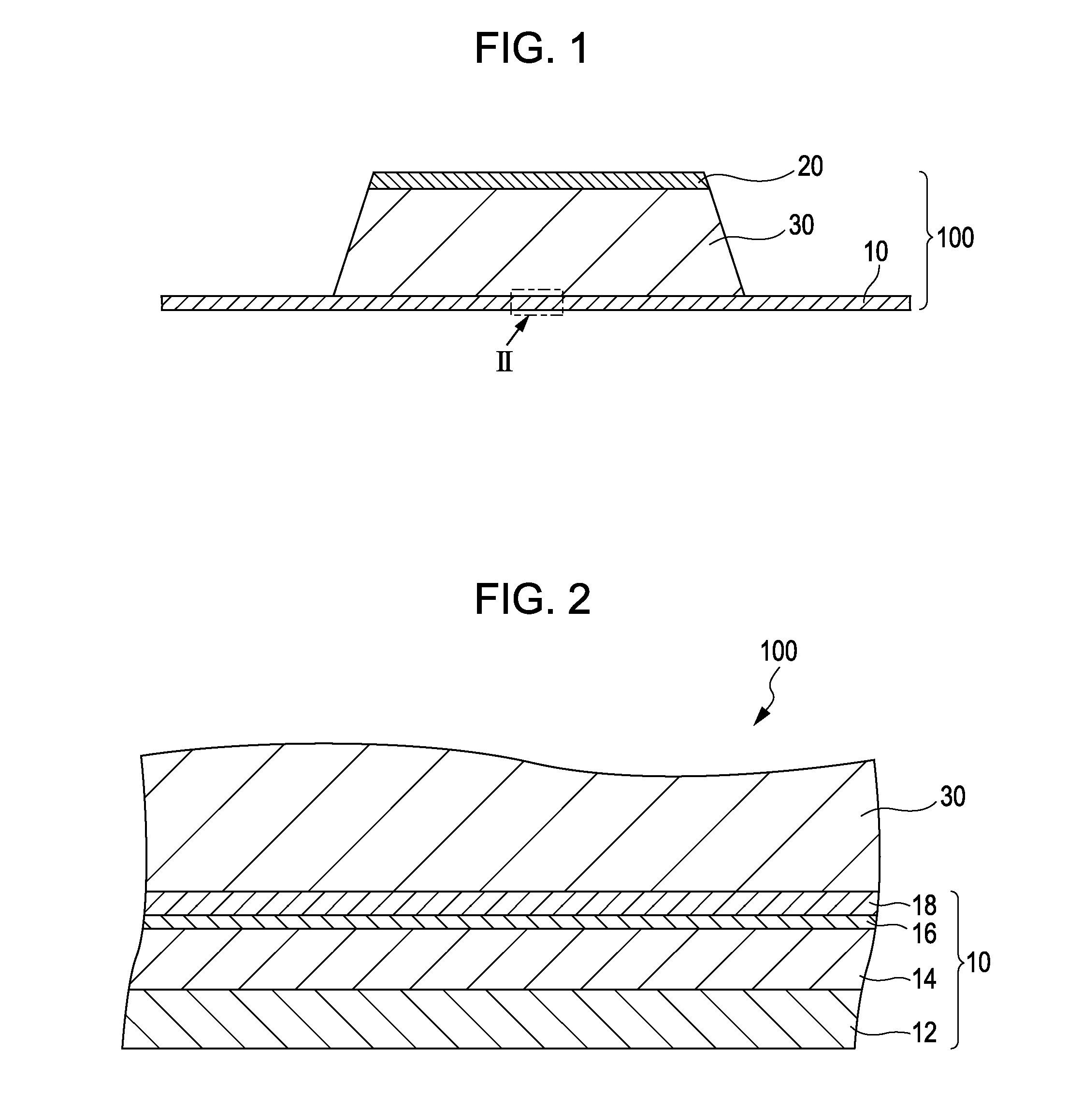
[0042]FIG. 1 is a cross-sectional view schematically illustrating a piezoelectric device 100 according to an embodiment of the invention. FIG. 2 is a cross-sectional view schematically illustrating part of the piezoelectric device 100 according to the embodiment in an enlarged manner.

[0043]The piezoelectric device 100 according to the embodiment includes a first electrode 10, a second electrode 20, and a piezoelectric layer 30.

1-1. First Electrode

[0044]The piezoelectric device 100 has the two electrodes, and the first electrode 10 is one of the two electrodes as illustrated in FIG. 1. The first electrode 10 is provided so as to...


PUM


Abstract

A piezoelectric device includes a first electrode and a facing second electrode, with a piezoelectric layer therebetween. The first electrode includes a first conductive layer, a first intermediate layer that contacts the first conductive layer, a second intermediate layer that contacts the first intermediate layer, and a second conductive layer that contacts the second intermediate layer and the piezoelectric layer. The first conductive layer contains a metal and an alloy. The metal is Ti, Zr, Hf, V, Nb, Ta, Cr, Mo, W, Mn, Fe, Co, Ni, Cu, Ag, or Au, and the alloy contains at least one of the foregoing metals. The first intermediate layer contains a nitrogen compound. The second intermediate layer contains a metal and an alloy. The metal is Ti, Zr, W, Ta, or Al, and the alloy contains at least two of the foregoing metals. The second conductive layer contains a conductive oxide.

Description

[0001]The entire disclosure of Japanese Patent Application No. 2009-257030, filed Nov. 10, 2009 is expressly incorporated by reference herein.BACKGROUND[0002]1. Technical Field[0003]The present invention relates to a piezoelectric device, a piezoelectric actuator, a liquid ejecting head, and a liquid ejecting apparatus.[0004]2. Related Art[0005]For example, a piezoelectric device in which a crystallized ceramic material is disposed between two electrodes is utilized as a piezoelectric actuator. An example of the piezoelectric actuator includes a type in which a movable member such as a vibrating plate is actuated in a bending vibration mode. Such a piezoelectric actuator is utilized in an ink jet recording head, in which a pressure generating chamber that is in communication with a nozzle hole that ejects an ink liquid is partially formed with a vibrating plate and in which the vibrating plate is actuated by a piezoelectric device to pressurize ink that has been introduced into the ...

Claims


Application Information

Patent Timeline
IPC IPC(8): B41J2/045H01L41/047B41J2/055B41J2/135B41J2/14B41J2/16H01L41/09H01L41/18H01L41/187H01L41/22H01L41/29H01L41/319
CPCB41J2/14233B41J2/161B41J2/1634B41J2/1642H01L41/0973B41J2/1646B41J2202/03H01L41/047B41J2/1643H10N30/877H10N30/878H10N30/2047
Inventor OHASHI, KOJI
Owner SEIKO EPSON CORP
Learn More