Turbine Blade for Industrial Gas Turbine and Industrial Gas Turbine

Inactive Publication Date: 2013-12-05
HOKKAIDO UNIVERSITY +1
View PDF6 Cites 4 Cited by
  • Summary
  • Abstract
  • Description
  • Claims
  • Application Information

AI Technical Summary

Benefits of technology

[0088]To confirm the effects of the invention, each test piece was subjected to a high-temperature exposure test at 1100° C. for evaluation.
[0089]A test piece having a structure without the diffusion barrier layer 1 and the metal layer 2 as shown in FIG. 1 was produced in addition to the test pieces as shown in FIGS. 4 and 5. The blast treatment and the deposition of each of the bond coat 3 and the top coat 4 were performed under the same conditions as those in the Example shown in FIG. 4.
[0090]FIG. 6 shows a scanning microscopic photograph of a cross section of the test piece of the Example shown in FIG. 4 after the exposure at 1100° C. for 600 hr. As seen in this drawing, the substrate 5 in the Example does not have the secondary reaction zone (SRZ) that may degrade mechanical properties of the substrate 5, revealing that the diffusion barrier layer 1 effectively suppresses

Problems solved by technology

Thus, Al may diffuse from the bond coat to the substrate during high temperature service, causing formation of a secondary reaction zone (SRZ) in the substrate which may reduce strength of the substrate.
The alloy layer containing Ru or Re described in Patent Document 1, however, is increasingly decomposed at high temperature through a reaction of the substrate and the bond coat, and is thus failed to maintain the above-described effects.
In addition, the gas turbine blade has a unique issue, i.e. , has differences from an aircraft turbine blade that often includes a single crystal blade, as described below.
Hence, for example, while Patent Document 2 exemplifies formation of the barrier layer at high temperature (solution heat treatment temperature), such a process cannot be applied to

Method used


Image

  • Turbine Blade for Industrial Gas Turbine and Industrial Gas Turbine
  • Turbine Blade for Industrial Gas Turbine and Industrial Gas Turbine
  • Turbine Blade for Industrial Gas Turbine and Industrial Gas Turbine

Examples


Example

EXAMPLE 1

[0073]In the gas turbine member, a single-crystal heat-resistant alloy having a composition of Ni—7Cr—1Co—0.8Mo—8.8W—1.4Re—0.8Nb—8.9Ta—5.1Al—0.25Hf—0.07C—0.02B was casted into a rod, and the rod was mechanically processed into a diameter of one inch and a thickness of 3 mm, so that the substrate 5 was prepared. The composition of the alloy was within a particularly preferable composition range of the invention.

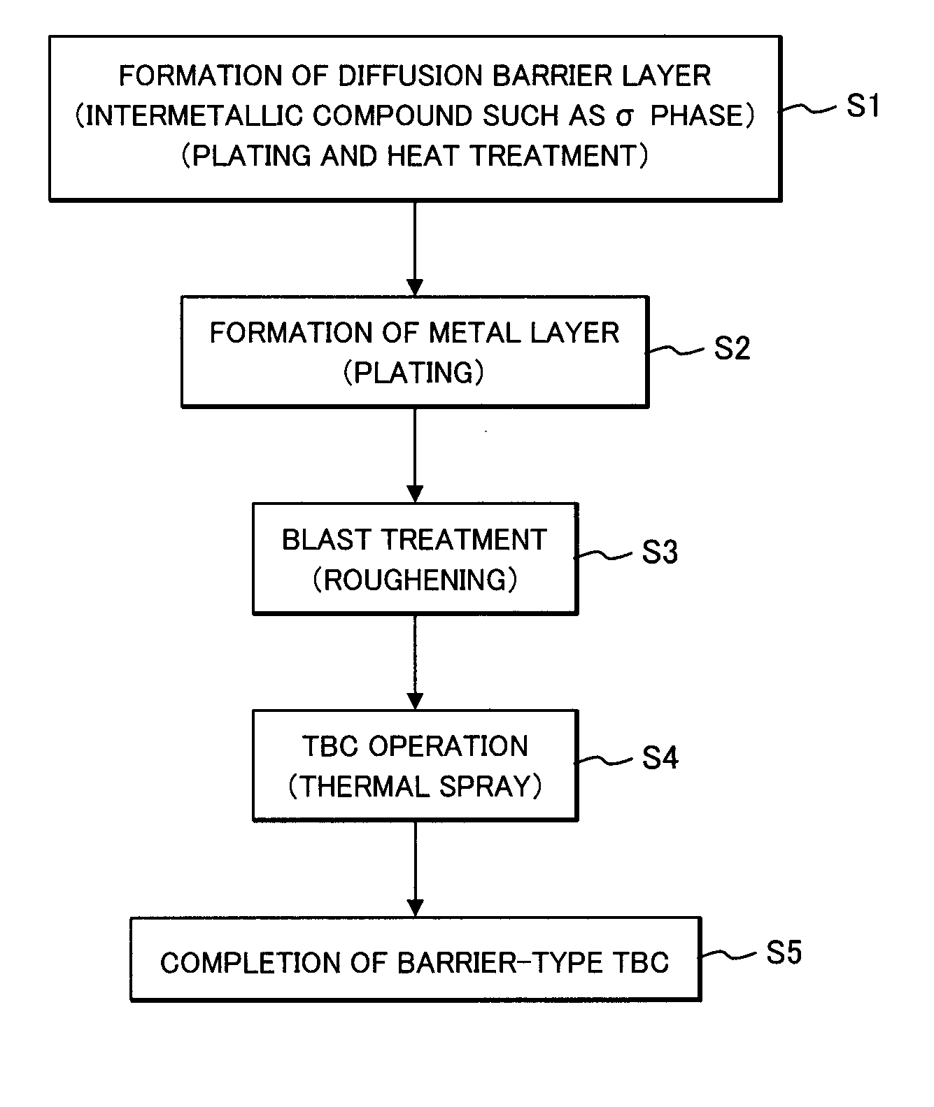
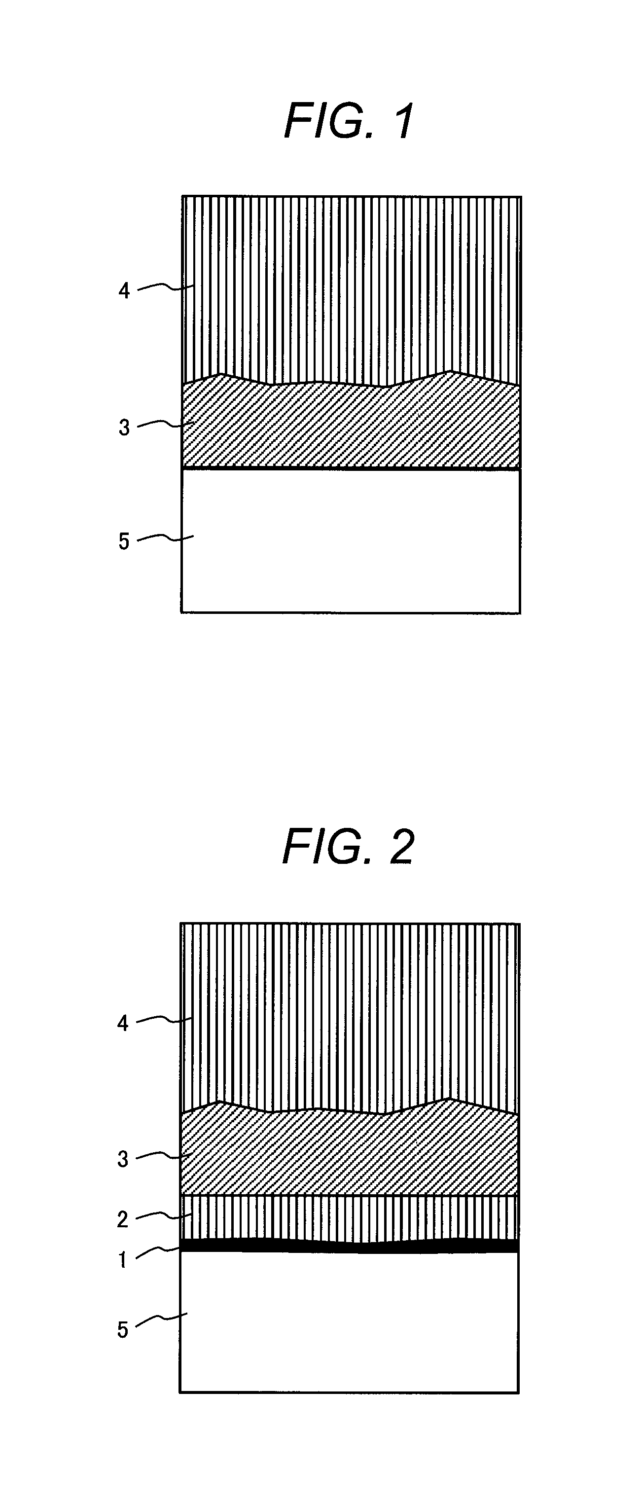
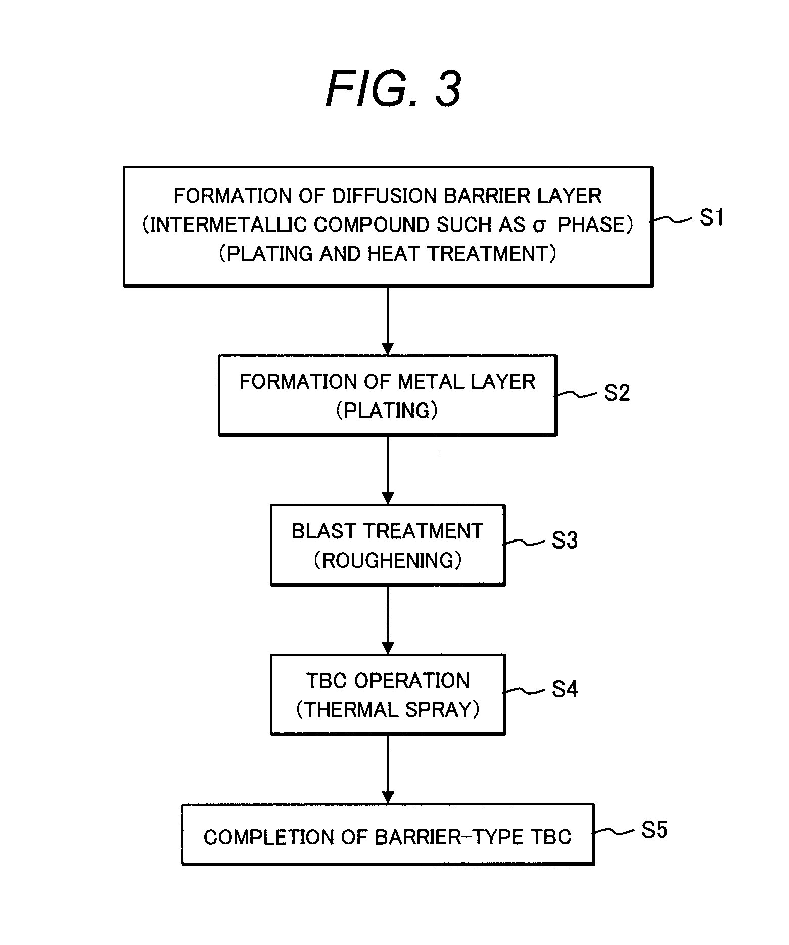
[0074]The surface of the substrate 5 was polished with #600 SiC waterproof abrasive paper, and then the substrate 5 was ultrasonically cleaned in acetone for degreasing. The diffusion barrier layer 1 was then deposited by an electroplating.

[0075]In this Example, electrolytic Ni plating was performed to precipitate a Ni layer on the surface of the substrate 5, and then the Ni layer was washed with distilled water, and then electrolytic Re plating was successively performed to precipitate a Re layer. Then, electrolytic Ni plating layers and electrolytic Re plating layer...

Example

EXAMPLE 2

[0093]The same coating as that in the Example 1 was formed on a surface of a first stage turbine blade 23 formed of a single-crystal heat-resistant alloy having the same composition as that of the Example 1, the surface being to be exposed to combustion gas, so that a turbine blade for industrial gas turbine was produced.

[0094]FIG. 8 shows an outline of an industrial gas turbine including the turbine blade for industrial gas turbine of the Example 1.

[0095]In this drawing, the gas turbine includes a compressor 11, a combustor 12, a turbine unit 13 (including a turbine blade and a turbine nozzle), and an exhaust outlet 14.

[0096]FIG. 9 shows a portion A in FIG. 8 in an enlarged manner, which is a cross-sectional diagram showing a detail of the turbine unit 13 including the turbine blade and the turbine nozzle.

[0097]In this drawing, the turbine unit includes a first stage shroud 21, a second stage shroud 22, a first-stage turbine blade 23, a second-stage turbine blade 24, a dis...


PUM

PropertyMeasurementUnit
Lengthaaaaaaaaaa
Fractionaaaaaaaaaa
Fractionaaaaaaaaaa

Abstract

A turbine blade for industrial gas turbine is used which includes a blade substrate formed of a single-crystal heat-resistant alloy containing C: 0.06 to 0.08%, B: 0.016 to 0.035%, Hf: 0.2 to 0.3%, Cr: 6.9 to 7.3%, Mo: 0.7 to 1.0%, W: 7.0 to 9.0%, Re: 1.2 to 1.6%, Ta: 8.5 to 9.5%, Nb: 0.6 to 1.0%, Al: 4.9 to 5.2%, Co: 0.8 to 1.2%, and the remainder substantially consisting of Ni with reference to mass, and includes a diffusion barrier layer, a metal layer, a bond coat, and a top coat, these layers and coats being stacked in this order on a surface of the blade substrate, the metal layer having a thickness of 5 to 30 μm. Thus, the turbine blade can be provided which has a thermal barrier coating formed without loss of a function of the diffusion barrier layer.

Description

CLAIM OF PRIORITY[0001]The present application claims priority from Japanese Patent application serial No. 2012-122810, filed on May 30, 2012, the content of which is hereby incorporated by reference into this application.BACKGROUND OF THE INVENTION[0002]1. Field of the Invention[0003]The present invention relates to a long-life turbine blade for industrial gas turbine including a blade substrate of a low-Re (low-rhenium) single crystal alloy, the blade substrate having a thermal barrier coating (TBC) thereon, and an industrial gas turbine including the turbine blade.[0004]2. Description of Related Art[0005]Recently, combustion gas temperature of a gas turbine has been increased to improve efficiency. Along with this, each of alloy members such as a turbine blade and a turbine nozzle has had the thermal barrier coating (TBC).[0006]The TBC includes a top coat as a thermal barrier formed of an oxide having a low coefficient of thermal conductivity. Such an oxide typically includes ytt...

Claims


Application Information

Patent Timeline
IPC IPC(8): F01D5/28
CPCF01D5/288C23C28/321C23C28/3215C23C28/3455C23C28/347Y02T50/60
Inventor IZUMI, TAKESHIARIKAWA, HIDEYUKIKOJIMA, YOSHITAKAMEBATA, AKIRAKASUYA, TADASHINARITA, TOSHIO
Owner HOKKAIDO UNIVERSITY
Why Eureka
Try Eureka