Passive compensating coupling laser device

a laser device and compensating technology, applied in the field of compensating coupling laser devices, can solve the problems of loss of efficiency, high cost, complex regulation loops, etc., and achieve the effect of reducing the cost of the regulation loop, and improving the efficiency of the regulation loop

Inactive Publication Date: 2003-09-25
OCLARO NORTH AMERICA
View PDF10 Cites 5 Cited by
  • Summary
  • Abstract
  • Description
  • Claims
  • Application Information

AI Technical Summary

Problems solved by technology

This loss of efficiency is directly related to the behavior of the semiconductor laser diode as a function of temperature.
This method achieves good results but the regulation loop is sophisticated and therefore costly.
This makes it unsuitable for use in inexpensive modules.
Using the above kind of mirror is unfortunately compatible only with Fabry-Perot lasers and not with distributed feedback (DFB) lasers.
The mirror has

Method used


Image

  • Passive compensating coupling laser device
  • Passive compensating coupling laser device
  • Passive compensating coupling laser device

Examples


Embodiment Construction

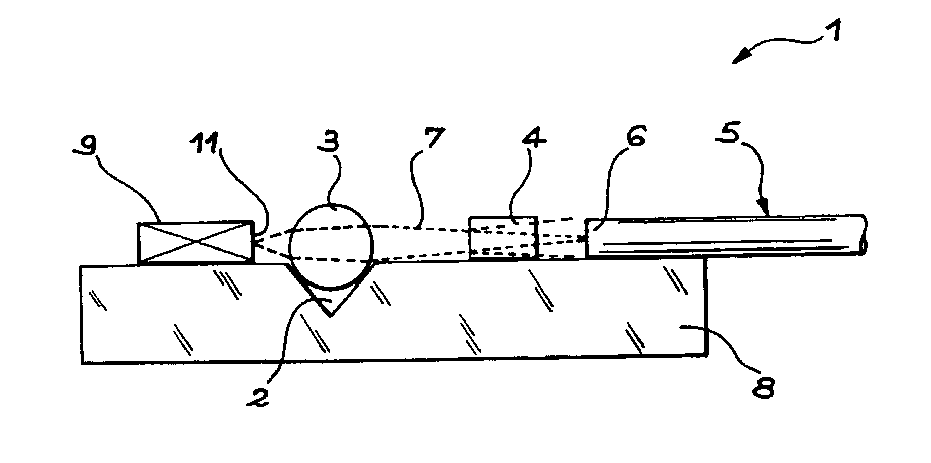
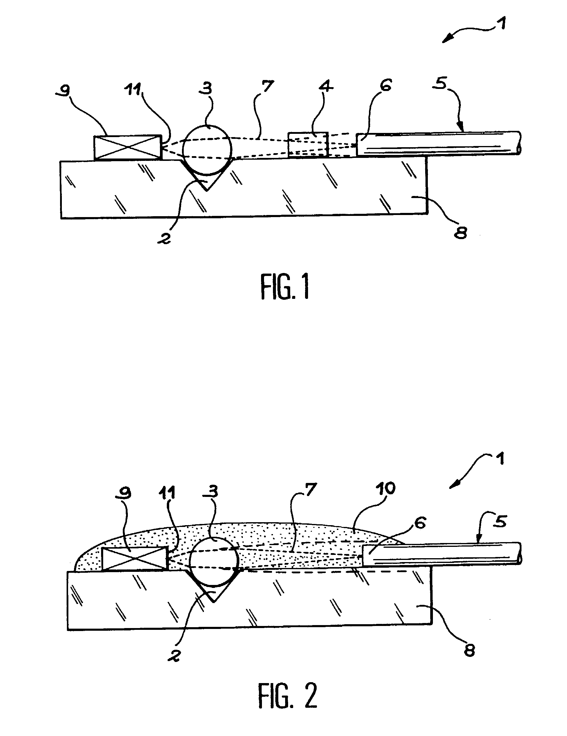
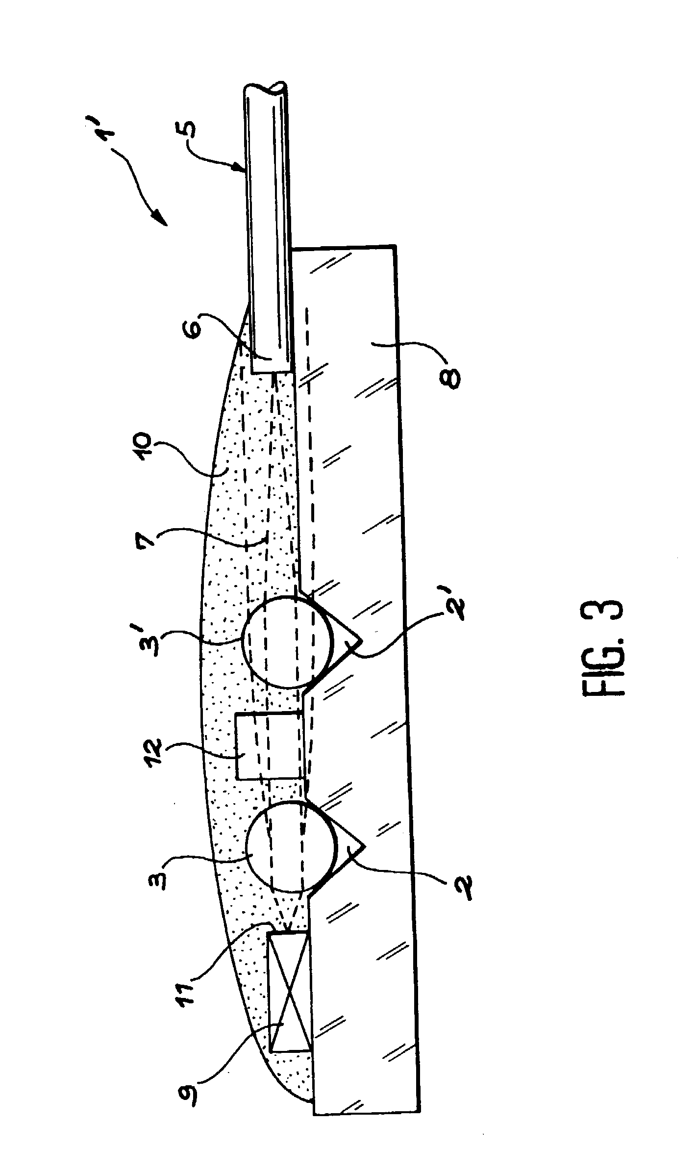
[0027] FIG. 1 represents a diagrammatic sectional view of a portion of a module 1. An optoelectronic component 9, for example a laser diode, is mounted on a base 8 in order to communicate with a laser fiber 5. This is known in the art.

[0028] According to the invention, a block 4 of a material having a refractive index that varies linearly with temperature is inserted in an optical path 7 and, when there is a lens 3 on the optical path, in series with the lens.

[0029] In the examples to be described it is assumed that the external efficiency of the laser decreases with temperature, which is the most usual case. The maximum coupling between the fiber 5 and the component 9 then corresponds to the highest designed operating temperature. The maximum coupling can be obtained with a medium whose index decreases as the temperature increases.

[0030] In the example shown the lens 3 couples an end 6 of the optical fiber and a face 11 of the laser diode 9. The lens 3 is placed at the bottom of a ...


PUM


Abstract

In an optical or optoelectronic module (1) an intermediate medium (4, 10) whose optical index decreases with temperature is introduced into the optical path (7) between a laser diode (9) and an optical fiber (5). This compensates, by passive means, the power losses of the laser emission due to the increase in operating temperature by improving the transmission between the diode (9) and the fiber (5). The intermediate medium (4, 10) is preferably deposited in the form of a capsule (10) enveloping the diode (9) and the end of the fiber (5). This achieves, by passive means, a transmitted power that is independent of the operating temperature.

Description

[0001] The invention relates to optoelectronic or optical systems including coupling means between an optical or optoelectronic component emitting a modulated or unmodulated laser wave and a waveguide for the emitted light, for example an optical fiber.PRIOR ART[0002] The laser diodes used in inexpensive optical modules, for example modules surface-mounted on a printed circuit (SML modules), have an external efficiency, i.e. a ratio between the variation of the power available at a fiber collecting the emitted optical power and the variation of the current injected into the laser diode, which is a function of the operating temperature of the module. Experimental results obtained with an SML module show a reduction in the external efficiency of the module by approximately three decibels when the temperature ranges from 25.degree. C. to 85.degree. C. This loss of efficiency is directly related to the behavior of the semiconductor laser diode as a function of temperature. With a consta...

Claims


Application Information

Patent Timeline
IPC IPC(8): G02B6/42H01S5/00H01S5/022
CPCG02B6/4201G02B6/4212G02B6/4239H01S5/02284H01S5/02228H01S5/02252H01S5/0064G02B6/4267G02B6/4253G02B6/424H01S5/02234H01S5/02326H01S5/02251
Inventor FERNIER, BRUNOKERBOEUF, SYLVAINERAINSANT, JEAN-MARCBOUBAL, FRANCOISGOTH, ALWINSCHERB, JOACHIM
Owner OCLARO NORTH AMERICA
Why Eureka
Try Eureka