Lift off cylinder for axial piston hydraulic pump

a hydraulic pump and axial piston technology, applied in the direction of mechanical equipment, fluid hybrid vehicles, engines with rotating cylinders, etc., can solve the problems of residual drag factor, seal, bearing, bearing, etc., and the system described, subject to several significant limitations,

Inactive Publication Date: 2003-09-25
PERMO DRIVE RES & DEV
View PDF9 Cites 6 Cited by
  • Summary
  • Abstract
  • Description
  • Claims
  • Application Information

AI Technical Summary

Problems solved by technology

The system as described, however, is subject to several significant limitations, many of which are common to previously known axial piston hydraulic motors and pumps.
In this regard, one significant limitation in the pump / motor assembly as previously described, relates to the inherent drag associated with the seals, bearings, valve faces and other elements that are in direct sliding contact with each other, as the cylinder block and other components in the rotational group rotate with respect to the valve plate, housing and other stationary components of the system.
Nevertheless, a residual drag factor remains, which consumes power, generates heat, and compromises the potential efficiency of the system.
While effective in preventing excessive leakage, the relatively high axial force between the cylinder block and the valve plate causes significant frictional drag between these components as they slide rotationally relative to one another, separated only by a thin film of pressurised oil.
The associated inefficiency is particularly significant in situations where the pump / motor assembly is operating in a neutral or "free-wheel" mode, in which the unit is neither pumping nor driving but is nevertheless rotating, often at high speed, as a result of direct connection with a rotary source of power or load.
While applying to some extent in almost any application of axial piston hydraulic motors and pumps, this limitation is particularly significant in the context of an PDS unit fitted to a vehicle, in the manner previously described.
In such situations, the RDS may do no effective work for prolonged periods, and yet introduce an inherent drag factor into the drive line, which ultimately compromises the efficiency of the power train of the vehicle.
Moreover, the basic problem is compounded in such conditions because the drag factor itself is exacerbated when the pump / motor unit is operating in the neutral or free-wheeling mode.
This is because the unit is not producing hydraulic pumping pressure sufficient to sustain the film of hydrostatic pressurised oil required to minimise the effect of frictional drag between the components in direct rotational contact with one another.

Method used


Image

  • Lift off cylinder for axial piston hydraulic pump
  • Lift off cylinder for axial piston hydraulic pump
  • Lift off cylinder for axial piston hydraulic pump

Examples


second embodiment

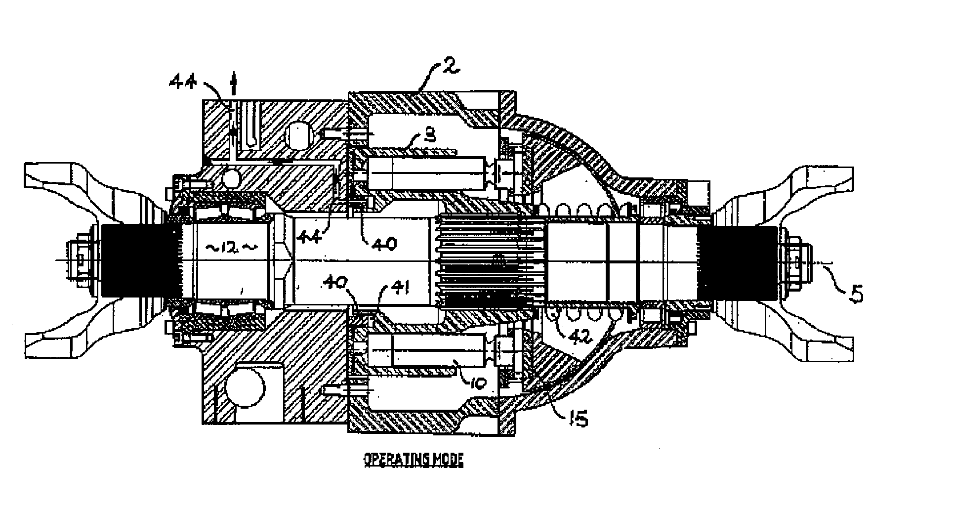
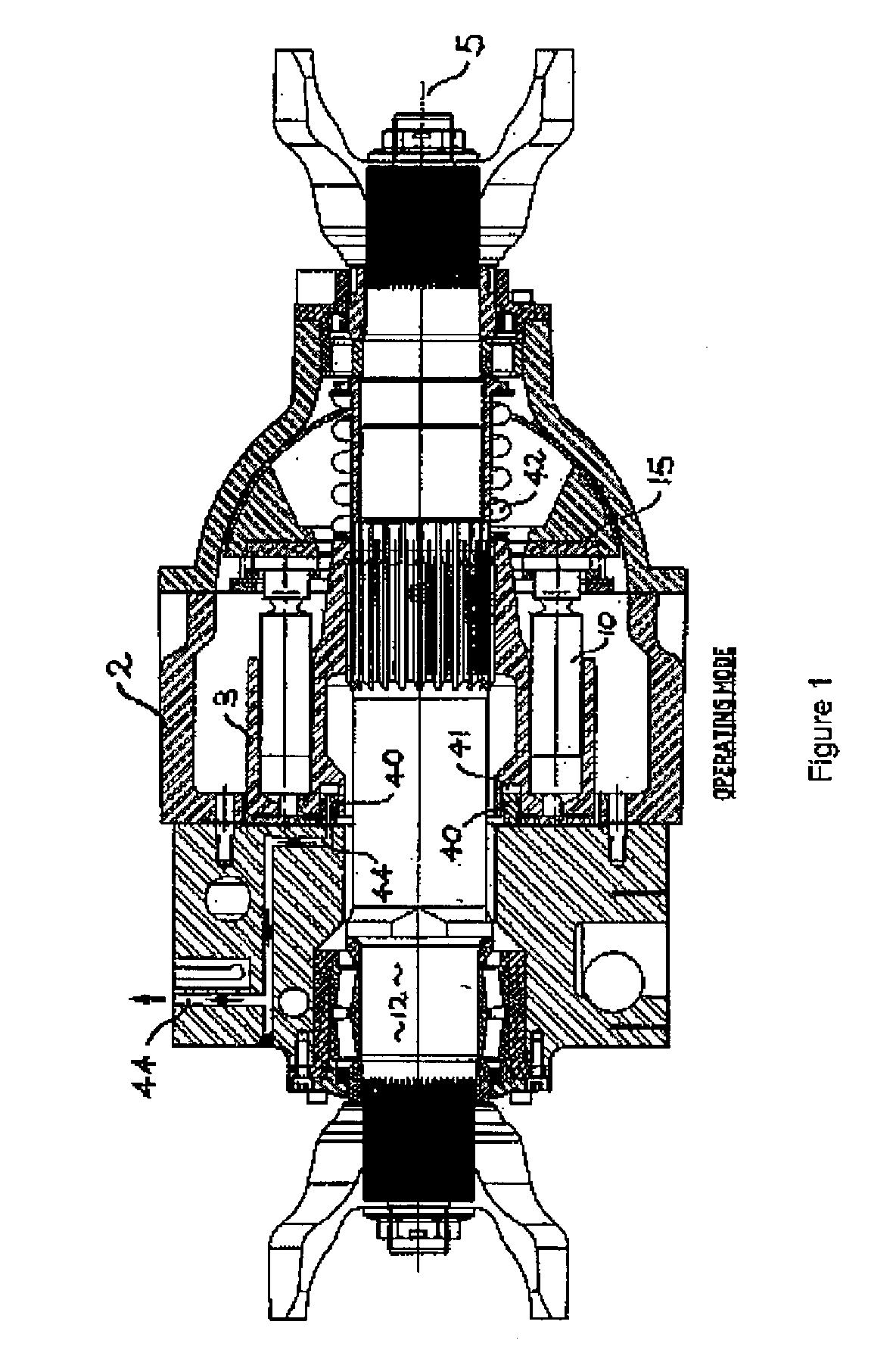
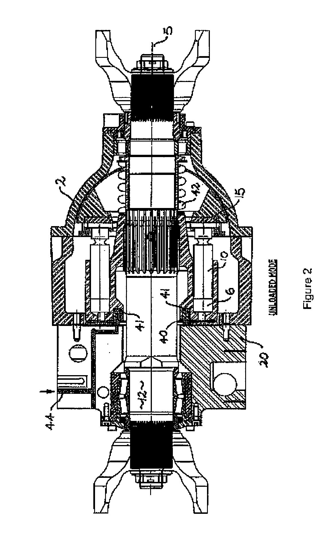
[0074] the invention is shown in FIGS. 3 and 4, wherein like features are denoted by corresponding reference numerals. In this embodiment, the pump / motor unit incorporates a secondary aspect of the invention, in the form of controllable bias means disposed to apply a variable bias force urging the mating faces 21 and 22 on the valve plate and the cylinder block respectively into sealing engagement. The bias means include an hydraulic hold-down piston 30 disposed within a complementary hold-down cylinder 32.

first embodiment

[0075] This active biasing mechanism is intended primarily to complement the operation of the lift-off cylinder as illustrated in the invention shown in FIGS. 1 and 2. For clarity of illustration, however, the lift-off mechanism is omitted from the embodiment shown in FIGS. 3 and 4.

[0076] Referring to FIGS. 3 and 4, the hold-down piston 30 takes the form of an annular sleeve disposed coaxially around the drive shaft, at the front (right-hand when viewing the drawings) end of the cylinder block, remote from the valve plate. The hold-down cylinder is correspondingly shaped, and is pressurised via a supply passage 35, which extends through the housing and the drive shaft as shown.

[0077] The pressure supplied to the hold-down cylinder is regulated by an electronic valve actuator 36 (represented diagrammatically in FIG. 3 only) according to predetermined operational parameters related to the pressure and flow characteristics of the pump / motor assembly and other characteristics of the sys...


PUM


Abstract

A positive displacement hydraulic pump/motor assembly (1) includes a rotary cylinder block (3) having a central axis (5) and a generally circular array of cylinders (6) disposed in parallel relationship around the axis. A corresponding plurality of axial pistons (10) is reciprocably disposed within the respective cylinders. A drive shaft (12) effects rotation of the cylinder block about the central axis and a drive plate (15) is disposed at one end of the cylinder block (3) to effect sequentially staggered reciprocation of the pistons (10) in response to rotation of the cylinder block. A stationary valve plate (20) is disposed at an opposite end of the cylinder block. The valve plate (20) includes a valve face (21) adapted for sliding rotational engagement with a complementary mating face (22) formed on the cylinder block. The valve plate further includes at least one inlet port (24) adapted for fluid communication with a source of hydraulic fluid and at least one outlet port (26) adapted for fluid communication with an hydraulic load. The ports (24, 26) are disposed such that in use, hydraulic fluid is progressively drawn into the cylinders in sequence as the respective pistons are displaced away from the valve plate and subsequently expelled from the cylinders as the pistons are progressively displaced toward the valve plate. The pump/motor assembly further includes lift-off means in the form of an hydraulic lift-off piston (40) and cylinder (41), selectively operable to displace the cylinder block marginally away from the valve plate, thereby to minimise rotational resistance between the respective mating valve faces (21, 22) under predetermined operational conditions. The pump/motor assembly is adapted for incorporation into an energy management system operable in a driving mode, a braking mode and a neutral motor to provide supplementary drive from regenerative braking in a vehicle.

Description

[0001] The present invention relates generally to hydraulic motors and pumps, and more particularly to positive displacement axial piston motors and pumps.[0002] The invention has been developed primarily for use with a pump / motor assembly which forms part of a regenerative drive system ("RDS"), and will be described predominantly hereinafter in that context. It should be appreciated, however, that the invention is not limited to this particular field of use, being readily adaptable to any axial piston hydraulic motor or pump for use in virtually any application.BACKGROUND TO THE INVENTION[0003] In the present context, the invention has been developed more specifically as an improvement to the RDS described by the present applicant in an earlier patent application filed via the Patent Cooperation Treaty (PCT) as international application No. PCT / AU99 / 00740, the full contents of which are hereby incorporated by reference.[0004] As previously described in that earlier patent applicati...

Claims


Application Information

Patent Timeline
Patent Type & Authority Applications(United States)
IPC IPC(8): B60K6/12F03C1/06F04B1/12F04B1/20
CPCB60K6/12F03C1/0607F03C1/0644Y02T10/6208F04B1/2007F04B1/2014F04B1/128Y02T10/62
Inventor RUSH, ALLAN
Owner PERMO DRIVE RES & DEV
Why Eureka
Try Eureka