Light source device using led, and method of producing same

a technology of light source device and led chip, which is applied in the direction of lighting and heating apparatus, instruments, display means, etc., can solve the problems of failure to provide failure to achieve the desired level of heat radiation effect, and the performance of led chip 2 will decline, etc., to achieve the effect of easy control, easy energized, and easy energized

Inactive Publication Date: 2003-10-09
SIGNIFY HLDG BV
View PDF5 Cites 454 Cited by
  • Summary
  • Abstract
  • Description
  • Claims
  • Application Information

AI Technical Summary

Benefits of technology

0037] It is preferable in the above that the sealing member is located closer to the radiator plate provided side than the other side of the insulating member, and that the side wall at the through hole of the insulating member is covered with a reflection for reflecting the light emitted from the LED chip in a desired direction. Accordingly, as the light emitted from the LED chip is fully diffused when passing through the sealing material, it can easily be controlled for distribution in a desired direction.
0038] In the improved light source apparatus, end portions of the wiring pattern are preferably extended to the radiator plate where they serve as external connector terminals. This allows the wiring pattern to be easily energized from the radiator plate side. While extension portions of the wiring pattern are extended to the radiator plate in various fashions, they may be arranged along the edges of the insulating member to reach the radiator plate. Alternatively, the insulating member may have through holes provided therein and filled with an electrically conductive material for extending the wiring pattern to the radiator plate. Also, the length of the wiring pattern to the radiator plate can be determined to match the requirement of a case as it may be extended to a midway on the insulating member or to the back side of the radiator plate or to a desired portion of the back side of the radiator plate or beyond the radiator plate.
0039] In the above, the end portions of the wiring pattern are preferably extended to the radiator plate provided side of the insulating member. Accordingly, the extension portions of the wiring pattern can easily be energized. It is assumed that the light source apparatus is mounted to a main system which has an opening for accepting the radiator plate. When the radiator plate is simply fitted into the opening of the main system, the extension portions of the wiring pattern which are extended to the radiator plate provided side of the insu

Problems solved by technology

This will decline the light pickup efficiency of the LED chip 2.
However, when the LED chip 2 is energized with a forward direction current greater than the rated level and thus driven under overload conditions, its performance will acceleratedly be declined by its own heat.
However, the passage of dissipating through the sealing resin 33 may fail to provide a desired level of the heat radiation effect because the thermal conductivity of

Method used


Image

  • Light source device using led, and method of producing same
  • Light source device using led, and method of producing same
  • Light source device using led, and method of producing same

Examples


embodiment 1

[0074] (Embodiment 1)

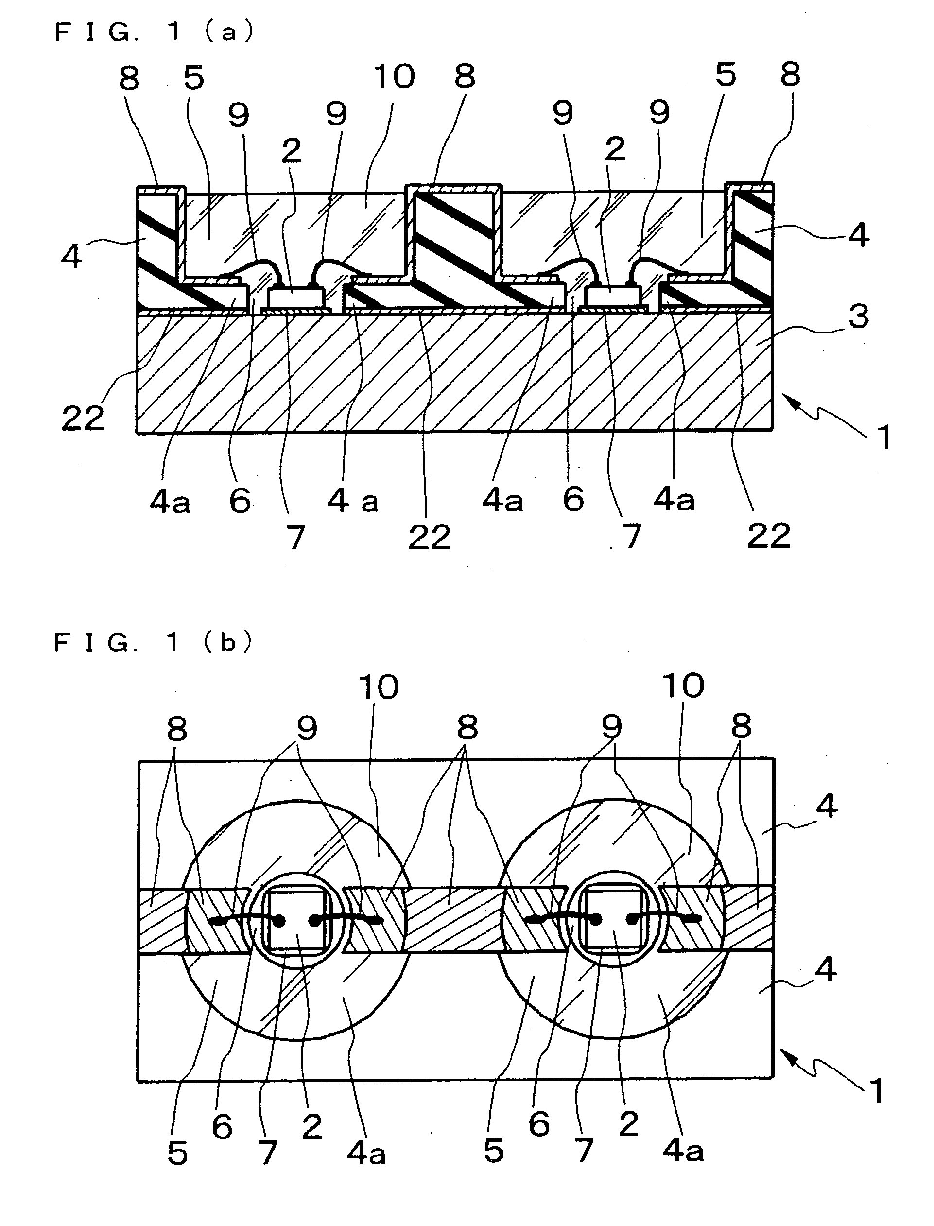
[0075] The description starts with Embodiment 1 referring to FIGS. 1a and 1b. A light source apparatus 1 of this embodiment includes a light emitting diode or a LED chip 2 for emitting the light. The LED chip 2 is thermally coupled at one side to a radiator plate 3 for radiation of heat from the LED chip 2 while the other side of the LED chip 2 emits the light.

[0076] The light source apparatus 1 has the radiator plate 3 made of, e.g., a substantially 2 mm thick thermally conductive material such as aluminum and joined by an adhesive 22 with an insulating member 4 made of, e.g., a substantially 2 mm thick insulating material such as liquid crystal polymer. The insulating material may be not only the polymer but a mixture of an inorganic material, such as aluminum or zirconium, and an (organic) binder processed through compounding, injection forming, degreasing (to remove the organic material), and baking.

[0077] The insulating member 4 has two round recesses 5 of ...

embodiment 2

[0083] (Embodiment 2)

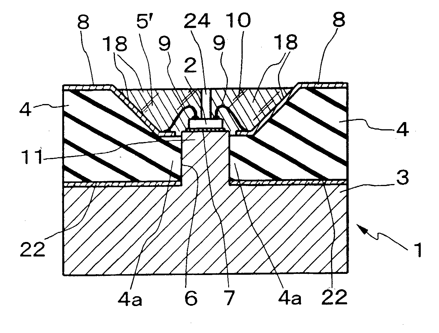
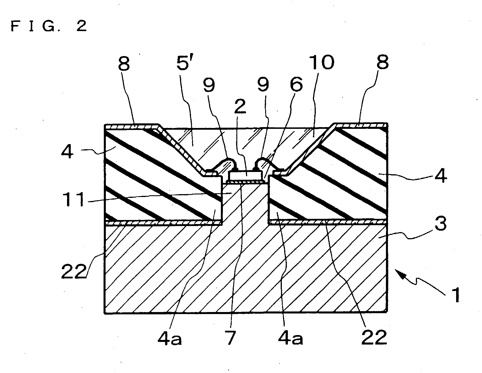
[0084] Embodiment 2 of the present invention will be described referring to FIG. 2. A light source apparatus 1 of this embodiment has a radiator plate 3 made of, e.g., a thermally conductive material such as aluminum and joined by an adhesive 22 with an insulating member 4 made of, e.g., a substantially 2 mm thick insulating material such as liquid crystal polymer.

[0085] The radiator plate 3 is fabricated by machining an aluminum sheet of substantially 3 mm thick. More particularly, the radiator plate 3 has a projection 11 of a substantially round column shape provided on the insulating member 4 side thereof which is about 1 mm in the diameter and about 0.9 mm in the height.

[0086] The insulating member 4 has a round recess 5' provided in the upper side thereof, where the radiator plate 3 is absent, to situate opposite to the projection 11 of the radiator plate 3. Also, the insulating member 4 has a through hole 6 provided in a center region at the bottom of the ...

embodiment 3

[0092] (Embodiment 3)

[0093] Embodiment 3 of the present invention will be described referring to FIG. 3a. A light source apparatus 1 of this embodiment is adapted in which the projection 11 of the radiator plate 3 similar to that in the light source apparatus of Embodiment 2 is about 1.1 mm in the height and its upper surface is flush with the top of the wiring pattern 8 disposed on the extension 4a of the insulating member 4. Since the other arrangement than the projection 11 is identical to that of Embodiment 2, like components are denoted by like numerals and will be explained in no more detail.

[0094] In the light source apparatus of Embodiment 2, some components of the light emitted from the LED chip 2 which are (horizontally) directed in substantially parallel with the upper surface of the LED chip 2 may be absorbed by or randomly reflected on the tilted wall of the extension 4a and hardly propagated towards the front, thus declining the efficiency of light emission. Advantageo...


PUM


Abstract

A light source apparatus which is improved in the efficiency of light emission thus to increase the operating life and the mechanical strength and a method of producing the same are provided. The light source apparatus 1 comprises a radiator plate 3 having thermally conductive properties, an insulating member 4 coupled to at least one side of the radiator plate 3 and having a through hole 6 provided in the side thereof facing the radiator plate 3, an LED chip 2 installed and thermally coupled to an exposed portion of the radiator plate 3 facing the through hole 6, an extension 4a inwardly projecting at the hole 6 from the radiator plate 3 end of the insulating member 4, a wiring pattern 8 provided on the insulating member 4 and electrically isolated by the insulating member 4 from the radiator plate 3, bonding wires 9 electrically connecting between portions of the wiring pattern 8 extended to the extension 4a and the electrodes of the LED chip 2, and a light-transmissive sealing material 10 filled in the through hole 6 for entirely encapsulating the LED chip 2 and the bonding wires 9.

Description

[0001] The present invention relates to a light source apparatus using a light emitting diode (LED) and a method of producing the same.[0002] One of such light source apparatuses is a bullet shaped LED lamp as shown in FIG. 24. The LED lamp may employ a single LED or an array of LEDs mounted on a lead frame 31.[0003] The bullet shaped LED lamp is commonly fabricated by die bonding an LED chip 2 into a recess 31a provided in a metal lead frame 31 using a die bonding paste 7 such as silver paste or epoxy resin. Then, the electrodes (not shown) provided on the LED chip 2 are wire bonded to the lead frames 31 and 32 by bonding wires 9 of a thread metal such as gold. Finally, the LED chip 2, the lead frames 31 and 32, and the bonding wires 9 are encapsulated in a light transmissible sealing resin 33.[0004] The sealing resin 33 is generally an epoxy resin material. The sealing resin 33 has three major functions. The first is a protective function. The sealing resin 33 protects the interna...

Claims


Application Information

Patent Timeline
IPC IPC(8): H01L25/075H01L33/64
CPCH01L25/0753H01L33/60H01L2224/45015H01L24/45Y10S362/80H01L2924/12041H01L2224/45144H01L2924/01068H01L2224/32245H01L2224/16225H01L24/97H01L2224/48227H01L2924/15165H01L2924/15153H01L2924/01079H01L2924/01078H01L2924/01029H01L2924/01013H01L33/642H01L33/647H01L2224/32188H01L2224/48091H01L2224/48465H01L2224/73265H01L2924/00014H01L2924/00H01L2924/00012H01L2924/12042H01L2924/181H01L2924/20752
Inventor SUGIMOTO, MASARUSHIOHAMA, EIJIKIMURA, HIDEYOSHIHASHIMOTO, TAKUMASUZUKI, TOSHIYUKINAKAGAWA, KAZUYAKOBAYASHI, MITSURUHASHIZUME, JIRO
Owner SIGNIFY HLDG BV
Why Eureka
Try Eureka