Transceiver method in a radio system and a radio system

a radio system and receiver technology, applied in the field of transmission methods in radio systems and radio systems, can solve problems such as interference that may vary, delay in transmission, interference for telecommunication, etc., and achieve the effects of reducing the interference level between signals, improving data rate, and improving reliability

Inactive Publication Date: 2003-10-23
NOKIA CORP
View PDF7 Cites 26 Cited by
  • Summary
  • Abstract
  • Description
  • Claims
  • Application Information

AI Technical Summary

Benefits of technology

0022] Thus, when using a method and radio system according to the invention, at least two signals comprising in general different data streams are transmitted via different paths. Owing to the polarization matching, these signals usually remain well separated. Thus, the interference level between the signals is lowered, whereby decoding is made more reliable.
0023] A significant advantage of the invention is also that when at least two different signals are transmitted, the data rate can be increased.

Problems solved by technology

In telecommunication connections, the transmission path used for transmission of signals causes interference for telecommunication, irrespective of the physical form of the transmission path.
Other simultaneous connections may also cause interference that may vary in the function of time and place.
In time diversity, interleaving and coding are used, with which time diversity is provided for the signal to be transmitted, but the disadvantage is that there will be delays in the transmission, particularly when the channel is slowly fading.
However, the method is inefficient when the coherence bandwidth of the channel is great.
The problem with MIMO methods has been that the channels must be rather uncorrelated relative to each other in order for the MIMO to function well.
The drawback of the MIMO method is thus that it does not function well in line-of-sight situations.
The problem with previous methods have been that in some cases, due to the incompatibility of the polarizations of the transmitter and the receiver, the signal does not reach its destination even if the transmission power is increased.
A corresponding problem may arise when signals are sent from antennas between which there is correlation.
As noted above, a prerequisite for good operation of the MIMO systems in use has been that the channels are rather uncorrelated relative to each other.
The problem with methods used previously has been that the signal does not reach its destination even if the transmission power is increased when the polarizations of the transmitter and the receiver are incompatible.

Method used


Image

  • Transceiver method in a radio system and a radio system
  • Transceiver method in a radio system and a radio system
  • Transceiver method in a radio system and a radio system

Examples


first embodiment

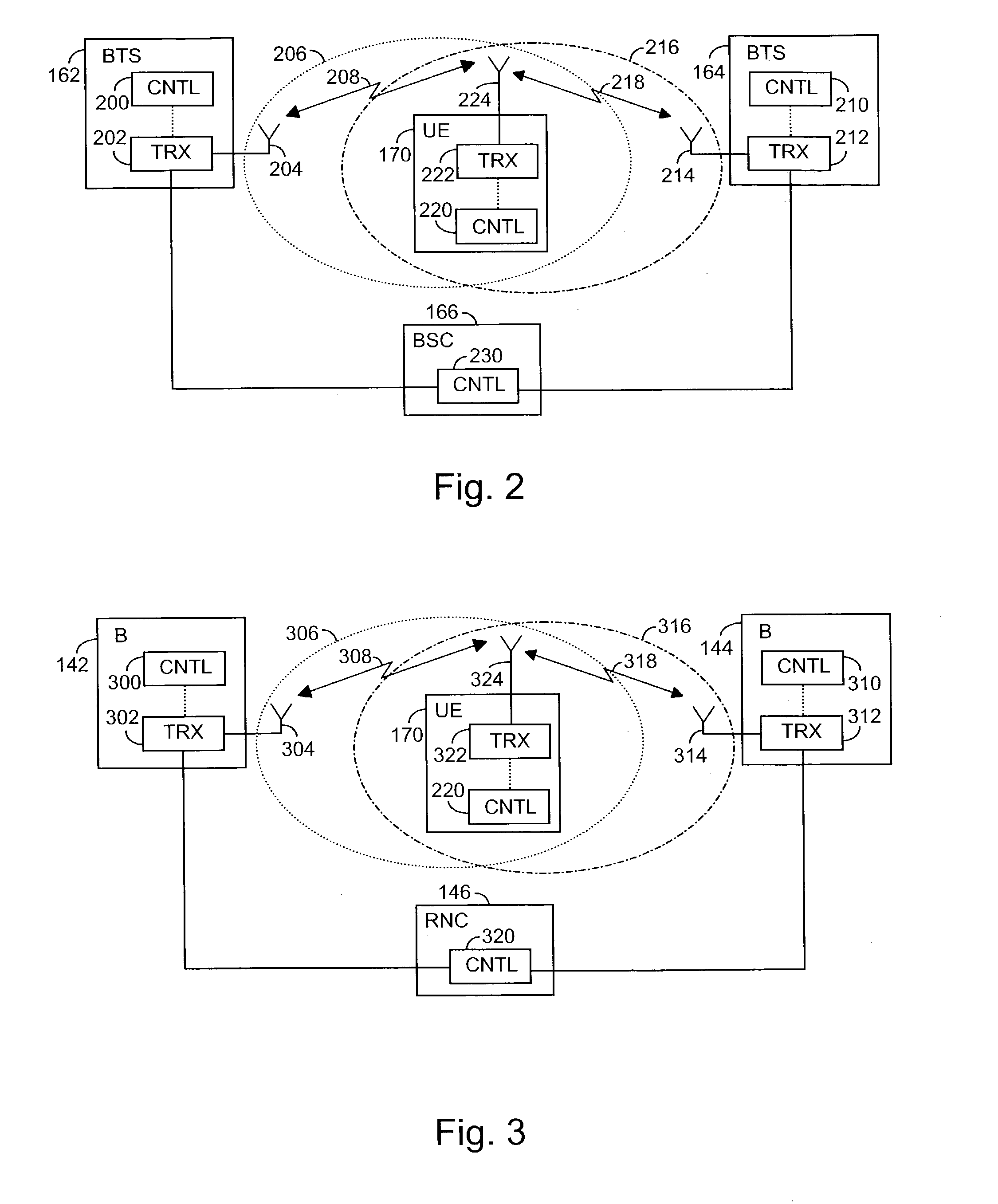
[0063] The first base transceiver station 142 comprises a transceiver unit 302, an antenna 304 and a control unit 300. In the same way, the second base transceiver station comprises a transceiver unit 312, an antenna 314 and a control unit 310. Also the radio network controller 146 comprises a control unit 320. The user equipment 170 also comprises a transceiver unit 322 and an antenna 324 for implementing a radio link, and a control unit 220. The transceiver units 302, 312, 320 utilize WCDMA technology. The antennas 304, 314, 324 and control units 300, 310, 320 can be implemented in the manner described in the

[0064] Use of Polarization Matching in MIMO Method According to the Invention

[0065] Next, the use of polarization matching in the MIMO method according to the invention is illustrated by means of an example. Let us assume that the base transceiver station transmits two different data streams s and z, sending these two different signals through two separate pairs of polarizatio...

embodiment example

[0087] In the following, an embodiment of a transceiver method, i.e. transmitting-receiving method, is studied with reference to FIG. 4a. In the example of the figure, the transceiver of the first type can be user equipment 170, typically a mobile station MS of a radio system, for example a mobile phone, and the transceiver of the second type is a base transceiver station of a radio system or a node B. The transceiver of the first type can also be for instance a portable computer or another terminal of a radio system. The use of the method is not restricted to such a situation, however, but can also be applied to an opposite case, where the transceiver of the first type is a base transceiver station in a radio system and the transceiver of the second type is a mobile station in a radio system.

[0088] The method is started from 400a. In 402a, at least one signal is transmitted by using a mobile station and at least one antenna, the signal being received by the base transceiver station...


PUM


Abstract

The invention relates to a radio system and a transceiver method. The method comprises transmitting (402a) a signal of at least one type by a transceiver of the first type; receiving (404a) a signal by a transceiver of the second type with at least two differently polarized antennas; performing (406a), by the transceiver of the second type, measurements of the received signal to determine its polarization; determining (408a) the polarization of the transceiver of the first type; adjusting (410a) the signal transmitted by the transceiver of the second type in such a way that the polarization of the signal is matched with the polarization used by the transceiver of the first type; transmitting (412a) at least two orthogonally polarized, polarization-matched signals by the transceiver of the second type; receiving (414a) the polarization-matched signals by the transceiver of the first type by using at least two antennas of different polarizations.

Description

[0001] 1. Field of the Invention[0002] The invention relates to a transceiver method in a radio system in which several antennas are used in the transmission and / or reception of a signal propagating through a radio channel, and a radio system implementing the method.[0003] 2. Description of the Related Art[0004] In telecommunication connections, the transmission path used for transmission of signals causes interference for telecommunication, irrespective of the physical form of the transmission path. The transmission path can be a radio link, an optical fibre or a copper cable, for example. In telecommunication utilizing radio links, in particular, situations often arise where the quality of the transmission path varies from one connection to another, and also during the connection. One typical phenomenon causing changes in the transmission channel is fading on the radio path. Other simultaneous connections may also cause interference that may vary in the function of time and place....

Claims


Application Information

Patent Timeline
Patent Type & Authority Applications(United States)
IPC IPC(8): H04B7/10
CPCH04B7/10
Inventor HAMALAINEN, JYRINIEMELA, KARIWICHMAN, RISTO
Owner NOKIA CORP
Why Eureka
Try Eureka