Multi-stage gas compressor system

Inactive Publication Date: 2003-11-20
ATLAS COPCO HURRICANE
View PDF5 Cites 15 Cited by
  • Summary
  • Abstract
  • Description
  • Claims
  • Application Information

AI Technical Summary

Benefits of technology

[0010] This invention provides multi-stage, high flow gas compressors providing increased reliability and efficiency, reduced size and reduced initial and operating costs. In the invention, a centrifugal blower is used to provide a first stage of compression and to delivery a flow of compressed air for further compression in one or more additional stages of compression.
[0015] A preferred two-stage embodiment of the invention comprises a gas compressor assembly including an internal combustion engine, a centrifugal blower driven by a mechanical connection from the internal combustion engine and providing a compressed gas output as a first stage of compression, and a rotary screw compressor driven by a mechanical connection from the internal combustion engine, having an input connected with the compressed gas output of the centrifugal blower and providing a second stage of compression. Such two-stage gas compressor assemblies permit the use of a smaller and less expensive diesel engine, as well as a smaller and less expensive rotary screw compressor. For example, such a preferred two-stage compressor can provide 750 cu. ft. per minute of compressed air at in excess of 100 psi gauge pressure, with a cost saving of about $8000, even with the additional costs of the centrifugal blower and an intercooler. The power required to drive such a two-stage gas compressor of the invention is 5% less than a conventional two-stage twin screw compressor of like capacity, and the weight of such portable two-stage gas compressor systems can be 1,500 lbs. lighter than a conventional portable compressor of similar performance. To achieve 750 cfm, the centrifugal blower must provide 18 psi. With larger centrifugal blowers and properly sized rotary screw compressors and engines, delivery of several thousand cfm may be achieved.

Problems solved by technology

By applying two specifically configured turbochargers in series to an engine-driven compressor such as that disclosed in U.S. Pat. No. 4,496,291, the output of the compressor can be increased by 33%; however, gains in performance of such systems are limited by the pressures and temperatures imposed on the engine exhaust system and only slight improvements can be further realized using current technology with the system of U.S. Pat. No. 4,496,291.

Method used


Image

  • Multi-stage gas compressor system
  • Multi-stage gas compressor system
  • Multi-stage gas compressor system

Examples


Embodiment Construction

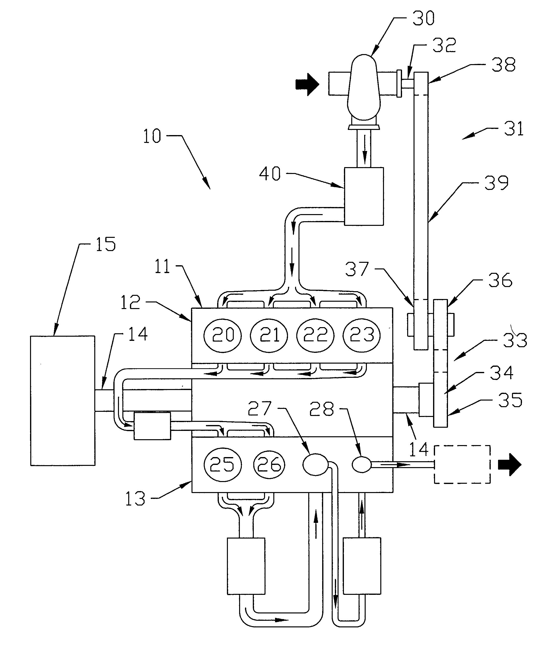
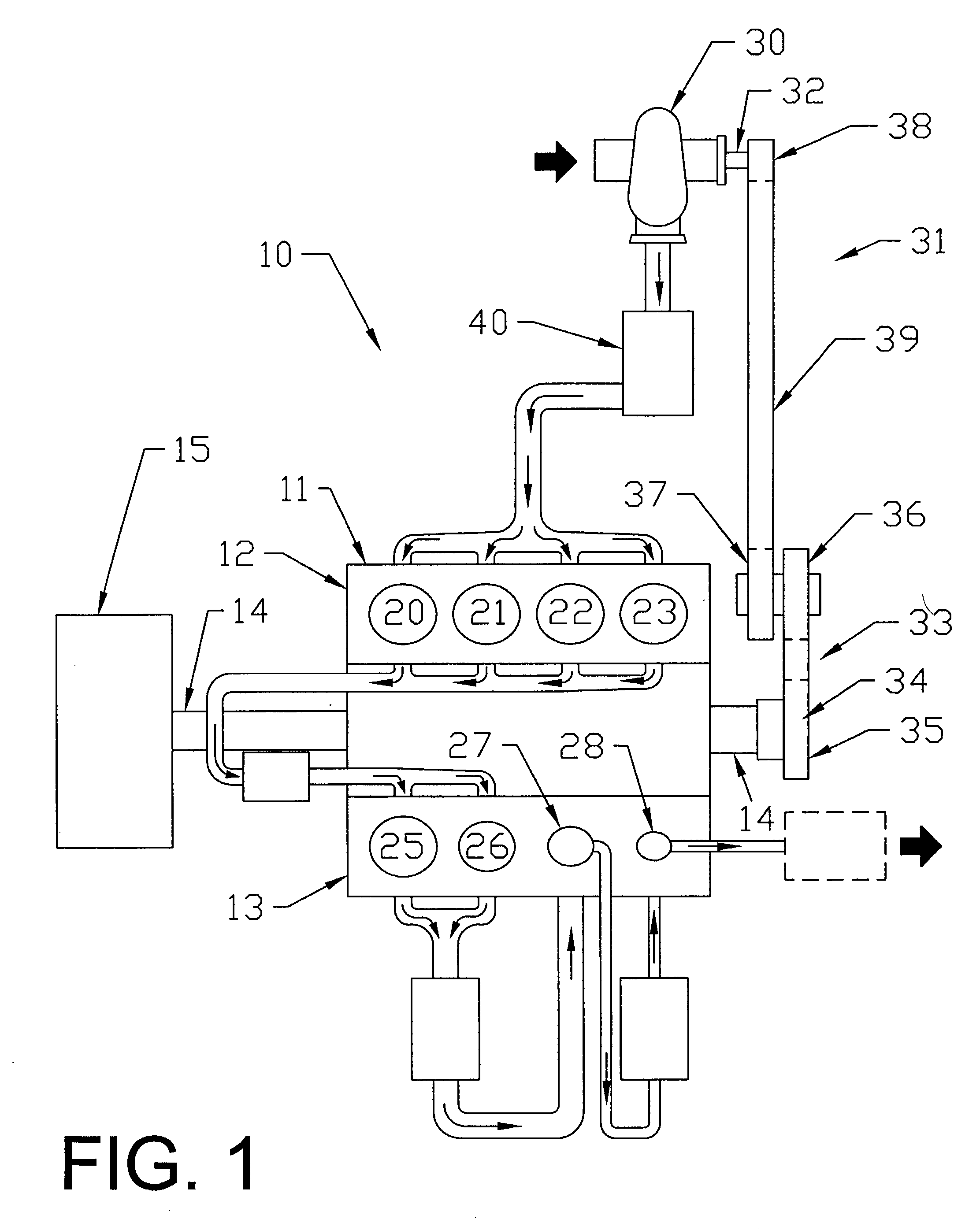
[0020] FIG. 1 is a diagrammatic illustration of one preferred compressor 10 of the invention. The compressor 10 illustrated in FIG. 1 includes an internal combustion engine block 11, which has a plurality of cylinders, with each of the cylinders containing a reciprocatable piston connected with and driven by a crankshaft 14 that may be driven by an external power source 15. In the compressor 10 of this invention, the internal combustion engine block 11 has been converted to be part of the multi-stage compressor 10.

[0021] In the preferred five stage compressor 10 illustrated in FIG. 1, the internal combustion engine block comprises a V-block, which includes eight cylinders with four cylinder-pistons 20, 21, 22, 23 in a first bank of cylinders 12 and four cylinder-pistons 25, 26, 27, 28 in a second bank of cylinders 13. Each of the cylinders is provided, as known in the art, with valve means to control the flow of gas into and out of the cylinders. The first bank of cylinders 12 in th...


PUM


Abstract

A multi-stage compressor comprises a gas compressor, a centrifugal blower having an input connected with a gas source and an output connected with the gas compressor and providing a flow of compressed gas as a first stage of compression to the gas compressor, and a power source mechanically connected with and driving both the centrifugal blower and gas compressor to provide multi-stage compression of said gas.

Description

[0001] This invention relates to multi-stage gas compressors for providing compressed gas at high flow rates and high pressures.[0002] Many varied construction and maintenance activities benefit from the use of portable engine-driven gas compressors. For example, in servicing oil and gas wells, compressed air at high flow rates and high pressures is used to blow collected debris that is interfering with the flow of oil or gas from the well, and compressed air, at substantially lower pressures, is used in maintaining structures exposed to the elements, for example, in sand blast cleaning and painting of steel bridges. Because such activities take place in remote locations, gas compressors are frequently engine-driven and carried by trailers or truck beds to the site of their use. Since the engine-driven gas compressors are operated in locations remote from sources of gasoline and diesel fuel, it is important that they provide maximal supplies of compressed gas with minimal fuel usage...

Claims


Application Information

Patent Timeline
IPC IPC(8): F04B25/00F04B41/06F04D25/02F04D27/00
CPCF04B25/00F04B41/06F04D27/02F04D27/00F04D25/02
Inventor GRIMMER, JOHN E.KETCHAM, EDWARD T.
Owner ATLAS COPCO HURRICANE
Why Eureka
Try Eureka