
Method and system for deterministic control of an emulation

a deterministic control and emulation technology, applied in the field of deterministic control of an emulation, can solve the problems of inability to handle system-level verification of complex soc designs, the single most time-consuming part of verification, and the challenge of verifying those designs becomes more difficul

Inactive Publication Date: 2003-12-04
AVAGO TECH WIRELESS IP SINGAPORE PTE
View PDF6 Cites 62 Cited by
  • Summary
  • Abstract
  • Description
  • Claims
  • Application Information

AI Technical Summary

Problems solved by technology

As system-on-chip (SOC) designs grow increasingly complex, the verification of those designs becomes more challenging.
Recent trends in the electronics industry appear to show that verification has become the single most time-consuming part of a SOC design schedule.
Conventional verification methods provide a means to test basic hardware functionality, but lack the throughput to handle system-level verification of complex SOC designs.
This lack is apparent in designs that integrate multiple components on a signal chip.
This lack exposes companies to substantial risks if design teams miss product delivery dates due to increased verification times, or worse, design errors that require expensive chip re-spins.
The increased productivity gained by this approach becomes insufficient, however, as the SOC design size increases.
This insufficiency in speed and efficiency reveals the verification bottleneck of simulating the register transfer level (RTL).
While this performance is excellent compared to software simulation solutions, it is still too slow for thorough system-level verification of SOCs.
This technique can also be extended to interactive data streaming applications, but the increased number of vectors required make the techniques cumbersome.
Data streaming performance is usually limited by the streaming / recording device to about 20-30 MHz for small width vectors in non-interactive applications.
This prototyping to thoroughly verify system integrity (hardware, firmware, and software) is not always practical or possible in cases where the target system is not readily available or where the target system can not be slowed down.
In many cases, slowing down a target system and other systems connected to it is the biggest impediment to the adoption of these verification methodologies.

Method used


Image

  • Method and system for deterministic control of an emulation
  • Method and system for deterministic control of an emulation
  • Method and system for deterministic control of an emulation

Examples


Embodiment Construction

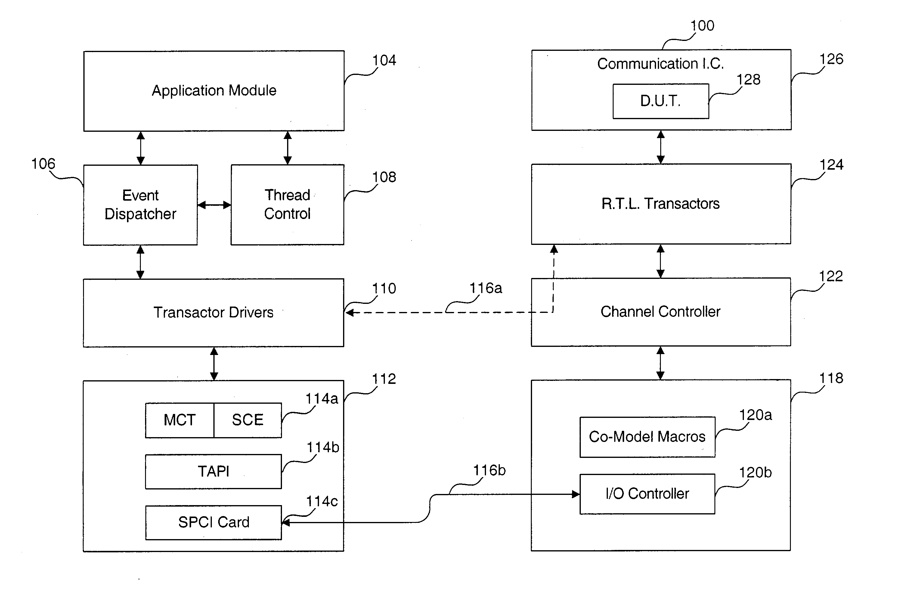
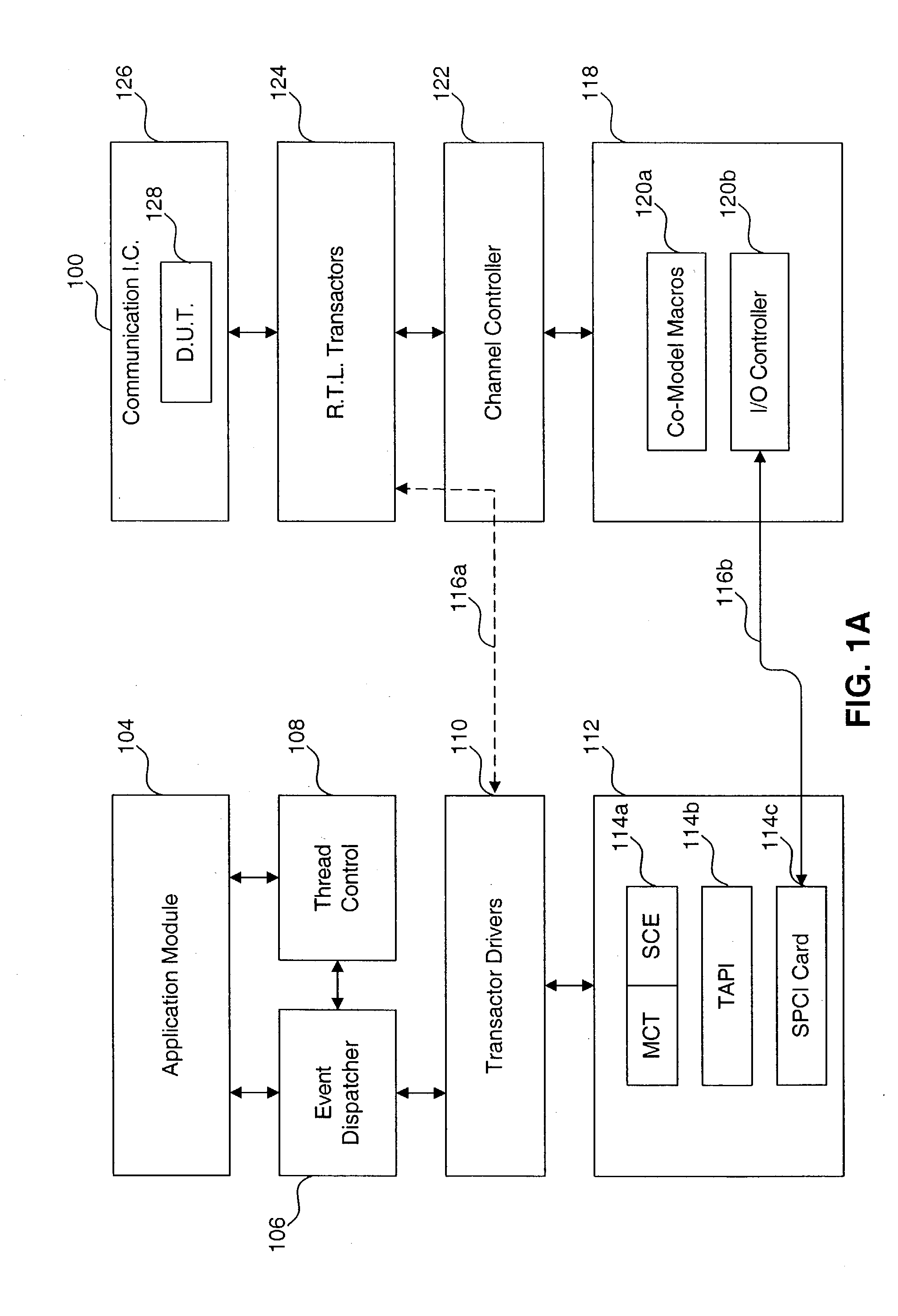
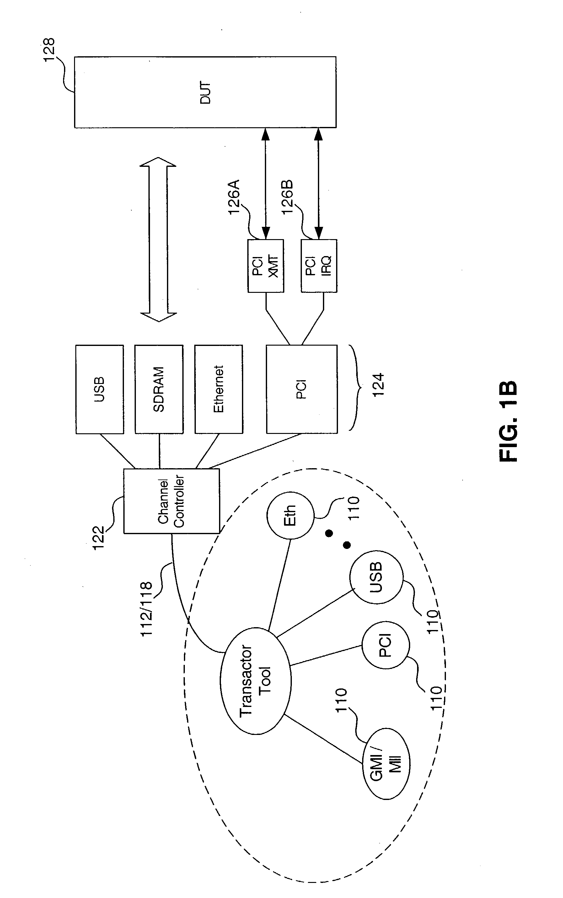
[0193] FIG. 12 is a block diagram of an example data processing unit 1200 useful for implementing items of the present invention. It is noted that the entities shown in FIGS. 1A-8B may be implemented using any number of data processing units 1200, and the configuration actually used is implementation specific.

[0194] Data processing unit 1200 may represent personal computer(s), hand held computers, workstation(s), and / or any other type of data processing devices. Which type of data processing device used to implement entities shown in FIGS. 1A-8B is implementation specific.

[0195] Data processing unit 1200 includes a communication medium 1202 (such as a bus, for example) to which other modules are attached.

[0196] Data processing unit 1200 includes one or more processor(s) 1204, and a main memory 1206. Main memory 1206 may be RAM, ROM, or any other memory type, or combinations thereof.

[0197] Data processing unit 1200 may include secondary storage devices 1208, such as but not limited t...


PUM


Abstract

An emulation-based event-wait simulator including an application module to configure and command verification processes on a design under test (DUT). An event dispatcher is in communication with the application module to deliver commands to the DUT. A plurality of transactors are in communication with the event dispatcher to forward the commands to the DUT. A channel controller is in communication with the transactors to process and forward the commands to the DUT, wherein the channel controller also receives messages from the DUT, processes the messages, and forwards the messages to the transactors for delivery to the event dispatcher and the application module.

Description

[0001] This application claims priority to commonly assigned U.S. Provisional Patent Application No. 60 / 384,390, filed Jun. 3, 2002, and to commonly assigned U.S. Provisional Patent Application No. 60 / 430,048, filed Dec. 2, 2002, entitled METHOD AND SYSTEM FOR DETERMINISTIC CONTROL OF AN EMULATION, which are incorporated by reference herein in their entirety.[0002] This invention relates generally to system and ASIC design verification, and more specifically, to deterministic verification techniques.RELATED ART[0003] As system-on-chip (SOC) designs grow increasingly complex, the verification of those designs becomes more challenging. Recent trends in the electronics industry appear to show that verification has become the single most time-consuming part of a SOC design schedule. Thus, there is a need for broader, deeper system-level verification.[0004] Conventional verification methods provide a means to test basic hardware functionality, but lack the throughput to handle system-lev...

Claims


Application Information

Patent Timeline
Patent Type & Authority Applications(United States)
IPC IPC(8): G06F17/50
CPCG06F17/5022G06F30/33
Inventor GARCIA, LUISVREELAND, RUSSELL E.NOVAK, CHRISTOPHER B.MARASIGAN, GABRIEL G.ROUSSEL, CHRISTOPHER A.
Owner AVAGO TECH WIRELESS IP SINGAPORE PTE
Learn More