Apparatus and method for continuously removing air from a mixture of ground polyurethane particles and a polyol liquid

a technology of ground polyurethane particles and polyol liquid, which is applied in the direction of liquid degasification, centrifuges, separation processes, etc., can solve the problems of urea linkages in the polymer, limited resistance to applied load, and inability to recover the original shape slowly, so as to reduce the potential for bubble entrainment and facilitate cleanup and shutdown

Inactive Publication Date: 2003-12-25
MOBIUS TECH
View PDF38 Cites 15 Cited by
  • Summary
  • Abstract
  • Description
  • Claims
  • Application Information

AI Technical Summary

Benefits of technology

0037] A baffle 329 is affixed to conduit 321 and serves to keep liquid from splashing out of the bowl.
0038] The spinning bowl 310 is disposed within a vacuum chamber 325, which has front plate 326 and back plate 327 attached with gaskets to make the chamber vacuum tight. Plate 327 contains a bearing-and-seal assembly 340, through which shaft 346 rotates. Plate 326 optionally has a sealed sight glass 328 to allow viewing of the spinning bowl. Vacuum is applied to the chamber, for example through fitting 330. The low absolute pressure within the chamber prevents bubbles from being re-entrained in the liquid as it is picked up (333) and directed toward outlet 335. In one embodiment, the absolute pressure may be less that 500 mbar. In another embodiment, the absolute pressure may be less than 300 mbar. Finally, in yet another embodiment, the absolute pressure may be between about 1 and 300 mbar. Substantially bubble-free liquid is available from outlet 335. A drain 332 may be provided to facilitate cleanup and shutdown.
0039] Referring now to FIG. 5, a liquid is delivered to inlet 401. Inlet 401 is positioned near the top of the tank, while outlet 405 is at the bottom of the tank. This arrangement of inlet and outlet provides for desirable first-in-first-out operation of the tank, but presents the potential for entrainment of bubbles due to jetting or splashing of the liquid. Weir 402 prevents the liquid from jetting into the tank, rather the liquid is diverted such that it runs down the wall of tank 407. Flexible weir extension 403 keeps the liquid running down the wall of the tank even at low flow rates. Liquid runs between the extension 403 and the wall of tank 407, and sucks extension 403 against the wall. This avoids any liquid dripping, "raining", or otherwise falling through an air space between inlet 401 and free surface 406. Extension 403 may be made of flexible plastic sheet, for example.
0040] FIG. 5 depicts the tank 407 as partially full, as it would be during startup from an initially empty condition. During initial filling, the liquid has the furthest distance to travel from inlet 401 to the free surface 406, and there is potential for entrainment of bubbles. Forcing the liquid to run down the side of the tank with weir 402 and extension 403 greatly reduces the potential for bubble entrainment.

Problems solved by technology

In addition to being reversibly deformable, flexible foams tend to have limited resistance to applied load and tend to have mostly open cells.
"Semi-rigid" or "semi-flexible" foams are those that can be deformed, but may recover their original shape slowly, perhaps incompletely.
This reaction also generates heat and results in urea linkages in the polymer.
Further, the slurry must be free of entrained bubbles because they create an undesirable irregular cell structure in the foam, including holes and splits.
Such a natural de-gassing process takes a long time because the slurry has a high viscosity, generally about 500 to 20,000 mPa-s.

Method used


Image

  • Apparatus and method for continuously removing air from a mixture of ground polyurethane particles and a polyol liquid
  • Apparatus and method for continuously removing air from a mixture of ground polyurethane particles and a polyol liquid
  • Apparatus and method for continuously removing air from a mixture of ground polyurethane particles and a polyol liquid

Examples


Embodiment Construction

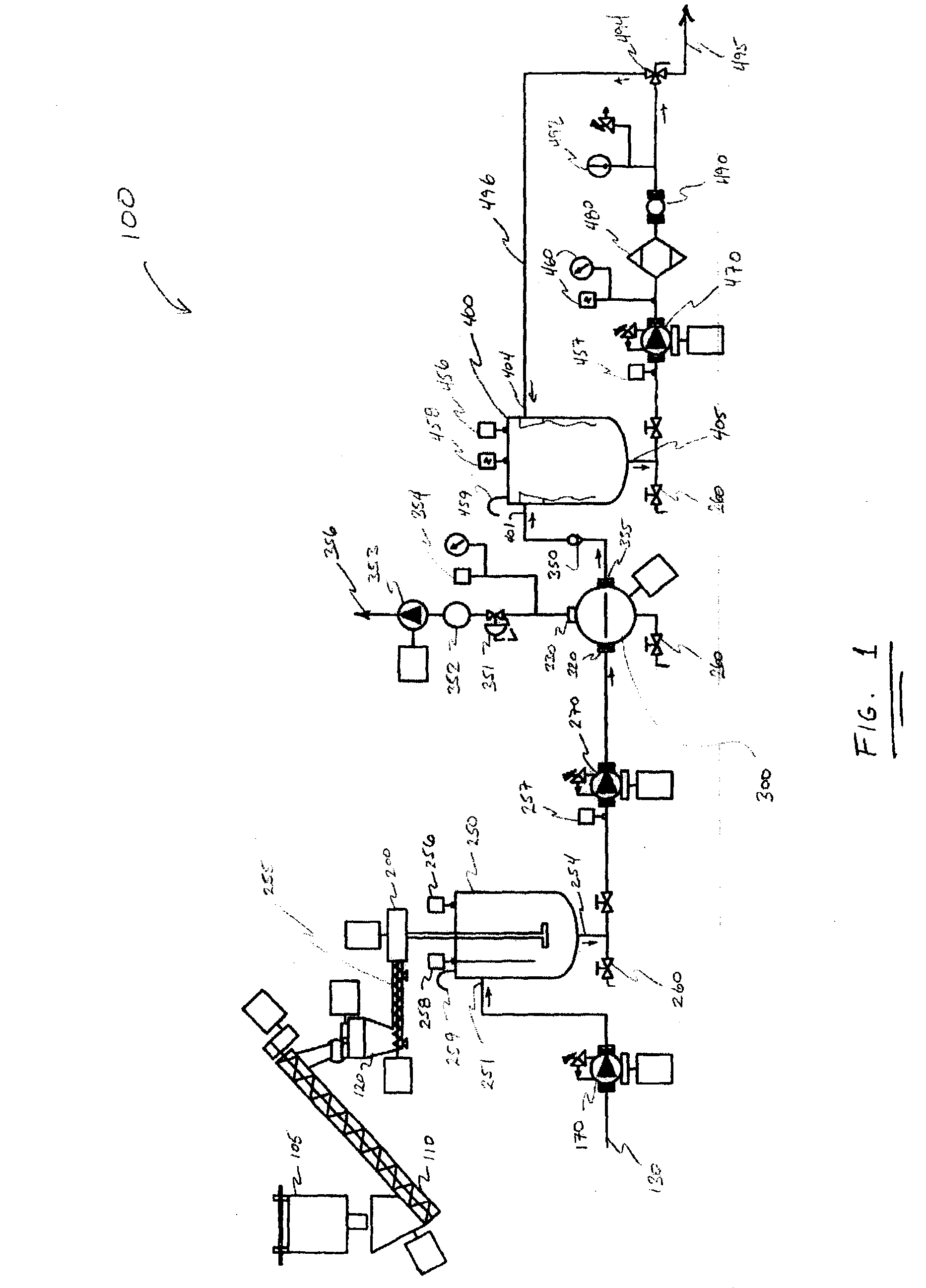
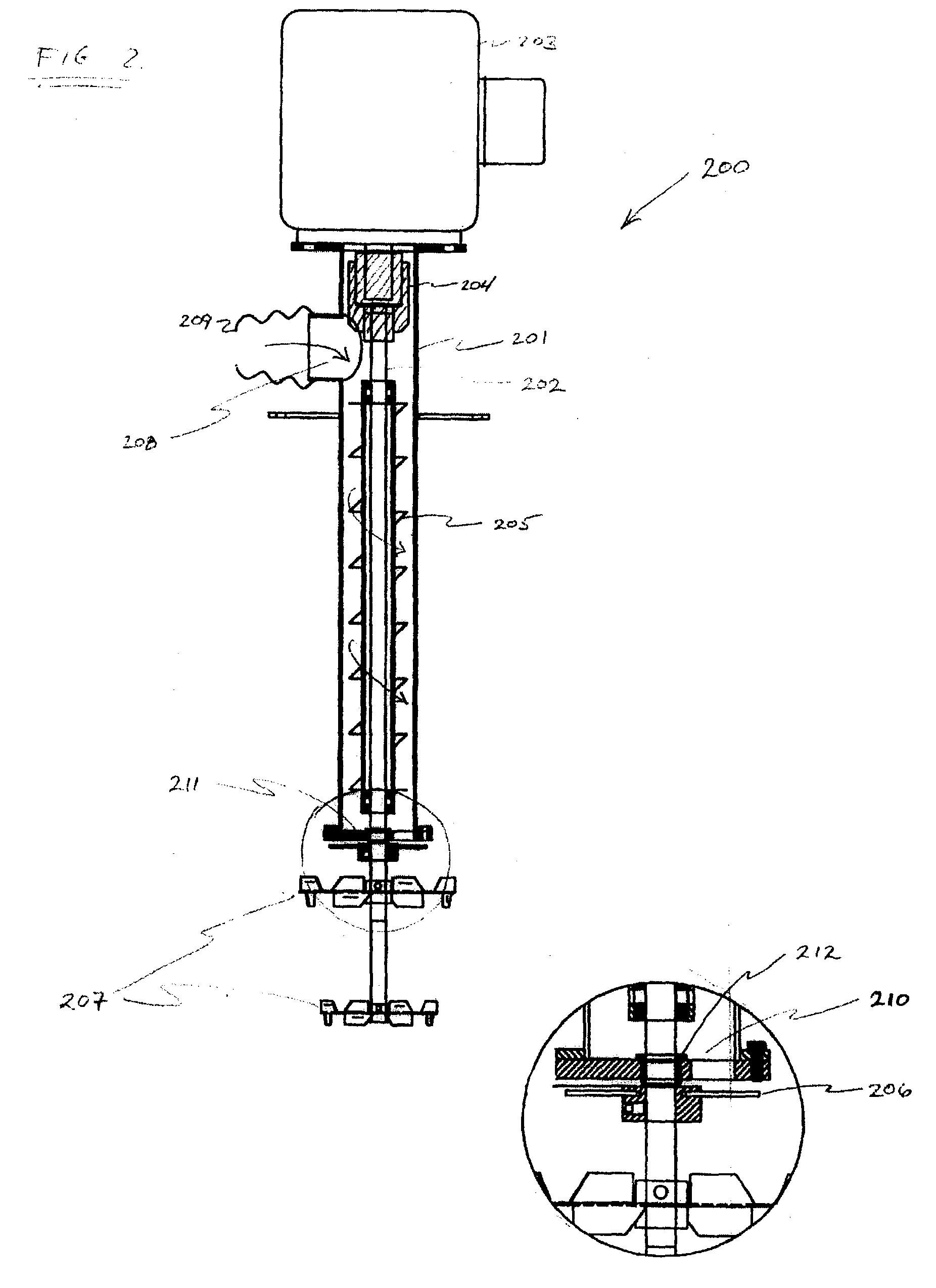
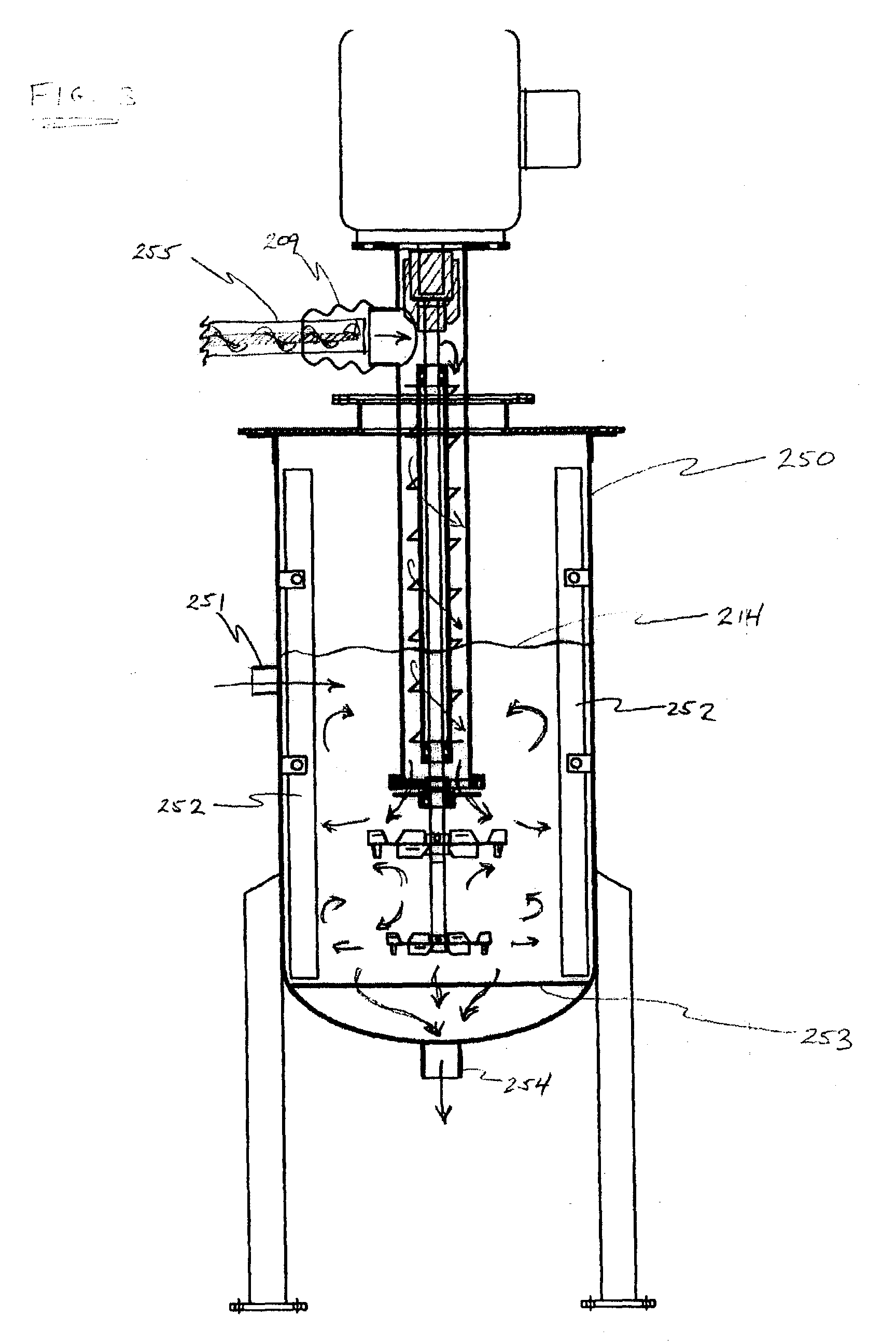
[0042] A mass of 83.5 kg of VORANOL 3010A polyether polyol from Dow Chemical Co. was initially charged to a 30-gallon mix tank. To this tank was added 16.7 kg of a powder of finely ground polyurethane foam with a maximum particle size of 250 microns. The initial batch was mixed thoroughly using the mixer shown in FIG. 2. The slurry obtained had a concentration of entrained air of about 10% by volume.

[0043] Using the process shown in FIG. 1, slurry was pumped from the mix tank, through the vacuum centrifuge and surge tank, and into a storage vessel. The concentration setpoint was 20 pphp (i.e., 20 parts of powder per 100 parts of liquid, or 16.7% by mass), and the flow rate setpoint was 20 kg / min of slurry. Samples of the slurry were taken as it left the process to go into the storage vessel. These samples were tested for slurry concentration by separating the powder from a known weight of slurry by means of filtering the powder from the slurry, washing away the polyol with methylene...


PUM

PropertyMeasurementUnit
absolute pressureaaaaaaaaaa

Abstract

The disclosed system comprises an apparatus and a method continuously removing air from a mixture of ground polyurethane particles and a polyol liquid. The apparatus for continuously removing air from a mixture of ground polyurethane particles and a polyol liquid comprises a deaerator having an inlet to receive a mixture of liquid and fine particles and an outlet to disperse the mixture. The deaerator further comprises a rotating bowl, wherein the bowl is attached to a shaft such that the bowl and the shaft rotate. The bowl has an inside and an outside surface that is coupled to the inlet of the deaerator to receive the mixture such that when the bowl is rotated, the mixture is spread on the inside surface of the bowl. A pickup tube is located in the bowl that catches the mixture and directs it through a conduit to the outlet. The rotation of the bowl imparts sufficient energy to the mixture to pump it through the conduit. A vacuum chamber that has a front plate and a back plate encompasses the bowl and the back plate contains an assembly by which the shaft rotates and the low absolute pressure within the vacuum chamber prevents bubbles from being re-entrained in the mixture as it is directed toward the outlet via the conduit.

Description

[0001] This application claims the benefit of U.S. Provisional Application 60 / 372,270, filed Apr. 11, 2002.BACKGROUND OF THE SYSTEM[0002] 1. Field of the System[0003] This system relates to devices and processes for continuously preparing mixtures of powdered solids in liquids, further relates to processes for continuous removal of entrained bubbles from such mixtures. The system is particularly useful for the preparation of bubble-free slurries of finely ground polyurethane-foam particles in polyol, and for the preparation of new polyurethane articles that contain the finely ground polyurethane-foam particles.[0004] 2. Background[0005] "Polyurethane" (PUR) describes a general class of polymers prepared by polyaddition polymerization of polyisocyanate molecules and one or more active-hydrogen compounds. "Active-hydrogen compounds" include water and polyfunctional hydroxyl-containing (or "polyhydroxyl") compounds such as diols, polyester polyols, and polyether polyols. Active-hydroge...

Claims


Application Information

Patent Timeline
Patent Type & Authority Applications(United States)
IPC IPC(8): B01D19/00B01F3/12B01F7/00B01F7/16B01F13/10B01F15/00B01F15/02B04B11/02B04B15/08B29B7/84F04D1/12
CPCB01D19/0063B01F3/1221B01F3/1271B01F7/1625B01F13/1013B01F13/1044B29B7/84B01F15/0085B01F15/00883B01F15/00954B01F15/0251B01F2003/0028B01F2013/1083B01F15/00837B29B7/845B01F23/023B01F23/59B01F23/53B01F27/81B01F33/81B01F33/8305B01F33/83612B01F35/511B01F35/513B01F35/531B01F35/181B01F35/71775B29B7/86B29B7/16B29B7/748B29B7/28B29B7/242B29B7/94
Inventor MARTEL, BRYAN LOUIS
Owner MOBIUS TECH
Why Eureka
Try Eureka