Forming method of cylinder cover

A cylinder head and exhaust port technology, which is used in the fields of liquid metal forming and cast iron metal material casting, can solve the problems of difficult to achieve equilibrium of casting solidification, difficult separation of molding sand and core sand, and poor fluidity, so as to avoid air entrainment and inclusion defects. , Conducive to orderly discharge, easy to operate

Active Publication Date: 2018-04-13
贵州英吉尔机械制造有限公司
View PDF9 Cites 13 Cited by
  • Summary
  • Abstract
  • Description
  • Claims
  • Application Information

AI Technical Summary

Problems solved by technology

The disadvantage is that the metal mold cavity needs to be preheated and sprayed with paint before pouring the molten metal to prevent mold cracking and difficult demoulding of castings. The operation steps are complicated and the quality stability is poor. Difficulty, the casting mold structure is usually the shape of the product and part of the inner cavity using a metal mold, and the shape of a part of the inner cavity is formed by a coated sand core, resulting in sand loss often occurring in the combination of the metal mold and the coated sand core, resulting in castings Sand inclusions appear
The advantage of the solid lost foam process is that the molding process is simplified, the operation of sand core and box closing is omitted, the raw and auxiliary materials of the molding are saved, and the workload of cleaning the casting is reduced. The disadvantage is that the polystyrene foam model and the model cluster are dip-coated Coating is a one-time consumption, can not be recycled and reused, the production cost is high, and it has an impact on environmental pollution
[0004] When the cylinder head of ferrous metal cast iron (inoculated cast iron, vermicular graphite cast iron or nodular cast iron) adopts the mold structure composed of green sand molding and coated sand core for gravity casting, since the green sand uses bentonite as binder and then water and Other additives are used for molding and making cores. The sand mold (core) does not need to be dried, and the molten metal is directly poured to form castings. The production efficiency is high, the cost is low, and it is suitable for mass production. It is one of the main casting production methods at present; Poor air permeability, low surface quality of castings, large investment in environmental protection measures, and cores need to be made of coated sand, resulting in difficulty in separating molding sand and core sand during casting shakeout, affecting subsequent sand treatment and molding quality
[0005] Although, in the existing casting process, there are already existing casting molds using coated sand to form castings. The sand box structure adopts two boxes for molding, then the lower core is assembled and the box is combined to form the mold cavity. Defects such as box, expansion box and floating core, the back sand filler chooses green sand, the air permeability of the mold is poor, and it is difficult to separate the green sand from the coated sand when the casting shakes out, which affects the subsequent sand treatment and molding quality, and the back sand filler also has Limestone sand is used. The sand has a large angular coefficient and poor fluidity. It is difficult to compact the mold during the molding operation. When the casting is sanded, it is easy to wear and cause dust pollution. The double-sided template is used for the molding of the coated sand casting mold. The wall thickness of the sand casting mold can be strictly controlled, but the disadvantage is that the air permeability is poor, and the vent holes need to be drilled in different parts, which increases the workload, consumes excess metal materials, makes it difficult to clean the casting, and the surface quality of the casting is reduced. The setting of the solid mechanism is realized by the weight of the upper box sand and pressed iron, so that the overall rigidity of the mold is low, the solidification of the casting is difficult to achieve balance, the amount of feeding required for the solidification of the casting is large, and the structure of the casting is prone to loose defects

Method used


Image

  • Forming method of cylinder cover
  • Forming method of cylinder cover
  • Forming method of cylinder cover

Examples


Embodiment 1

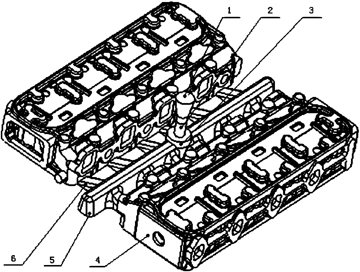
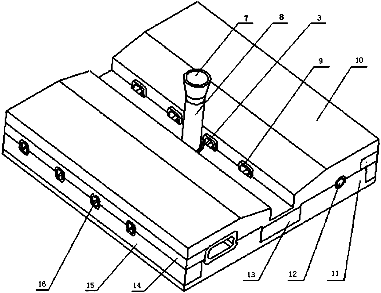
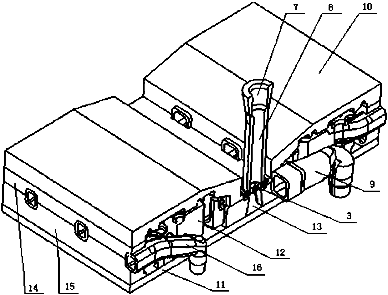
[0051] The composition and production of the coated sand mold: ①The composition of the mold: a total of 28 independent structural parts are assembled, which are the upper outer mold shell type 10, the lower outer mold shell type 11, and eight air inlet shells. Core 9, eight exhaust duct shell cores 16, two cooling water cavity solid cores 12, sprue cup 7, sprue 8, filter screen 3, horizontal-inner runner 13, two exhaust duct sides The solid core 14 of the core base and the solid core 15 of the lower core base on the side of the two exhaust passages; 2. The manufacturing method of 25 independent structural parts in the mold: there are three types of manufacturing, which are respectively shell molding, shell core manufacturing and Solid core production. Among them, the upper outer mold shell type 10 and the lower outer mold shell type 11 are made of shell molds: the templates of the upper half mold shell type and the lower half mold shell type are preheated to 180-220°C, and the...

Embodiment 2

[0057] The composition and production of the coated sand mold: ①The composition of the mold: a total of 16 independent structural parts are assembled, which are the upper outer mold shell type, the lower outer mold shell mold, four crankcase shell cores, two Valve lifter solid core, oil cooler solid core, cooling water cavity solid core, first cylinder side solid core, fourth cylinder side solid core, cylinder barrel solid core seat, sprue cup, sprue, filter ; ②Manufacturing of 16 independent structural parts of the mold: There are three types of manufacturing, which are shell mold making, shell core making and solid core making. Among them, the upper outer mold shell type and the lower outer mold shell mold are made of shell molds: preheat the templates of the upper outer mold shell mold and the lower outer mold shell mold to 200°C, and the coated sand will naturally fall into the preheated mold under the action of gravity. In the shell molding cavity formed by the single-sid...


PUM

PropertyMeasurementUnit
thicknessaaaaaaaaaa
surface roughnessaaaaaaaaaa
particle diameteraaaaaaaaaa

Abstract

The invention relates to a forming method of a cylinder cover, which is simple and convenient in process and good in effect. Manufacturing of an upper outer mold shell and a lower outer mold shell isas follows: a template is preheated to 180 to 220 DEG C, a coating film naturally falls into a forming cavity formed by the template and a sand blocking frame, the template is continuously heated to 250 to 260 DEG C and heat is preserved for 680 to 760 seconds; manufacturing of gas inlet channel shell cores and gas exhausting channel shell cores is as follows: a mold cavity is preheated to 180 to250 DEG C, film coating sand naturally falls into a core box mold cavity, the mold cavity is continuously heated to 275 to 285 DEG C and heat is preserved for 50 to 70 seconds; manufacturing of cooling water cavity solid cores, a pouring cup, a straight pouring gate, a transverse-inner pouring gate, an exhausting channel side upper core base solid core and an exhausting channel side lower core base solid core is as follows: the mold cavity is preheated to 180 to 260 DEG C, the film coating sand is blown into the mold cavity, the mold cavity is continuously heated to 280 to 290 DEG C and heat is preserved for 90 to 110 seconds; a film coating sand casting type structural component is subjected to coating, drying and assembling; a casting mold is modeled; alloy is smelted and inoculation isconducted; and gravity casting, solidification and separation are conducted. The forming method of the cylinder cover is suitable for manufacturing the cylinder cover.

Description

technical field [0001] The invention relates to the technical field of cast iron metal material casting, in particular to a production method of an engine cylinder head casting, in particular to a casting mold for making a cylinder head, its shape and a pouring and solidification forming method, and belongs to the technical field of liquid metal forming. Background technique [0002] The production methods of traditional engine cylinder head castings are as follows according to different materials: gravity casting of metal molds for aluminum alloy cylinder heads, low pressure casting of metal molds and production methods of solid lost foam casting; black Metal cast iron (inoculated cast iron, vermicular graphite cast iron or nodular cast iron) cylinder head uses green sand molding and coated sand core combined casting mold structure for gravity casting forming, solid lost foam casting forming and double-sided mold forming coated sand shell molding Gravity casting production ...

Claims


Application Information

Patent Timeline
Patent Type & Authority Applications(China)
IPC IPC(8): B22C9/02B22C9/10B22C1/00B22C21/08B22C9/08
CPCB22C1/00B22C9/02B22C9/082B22C9/103B22C21/08
Inventor 王新节蒋勤南蒋伟钟王鹏飞张俊邵威吴央芳
Owner 贵州英吉尔机械制造有限公司
Why Eureka
Try Eureka