Method, system and facility for controlling resource allocation within a manufacturing environment

a technology of resource allocation and manufacturing environment, applied in the direction of total factory control, programme control, electric programme control, etc., can solve the problems of high production cost, difficult or impossible to market at a profit, and risky prediction of customer demand, so as to reduce production costs

a technology of resource allocation and manufacturing environment, applied in the direction of total factory control, programme control, electric programme control, etc., can solve the problems of high production cost, difficult or impossible to market at a profit, and risky prediction of customer demand, so as to reduce production costs

US20040010334A1Inactive Publication Date: 2004-01-15DELL PROD LP

Image

  • Method, system and facility for controlling resource allocation within a manufacturing environment
  • Method, system and facility for controlling resource allocation within a manufacturing environment
  • Method, system and facility for controlling resource allocation within a manufacturing environment

Examples


Embodiment Construction

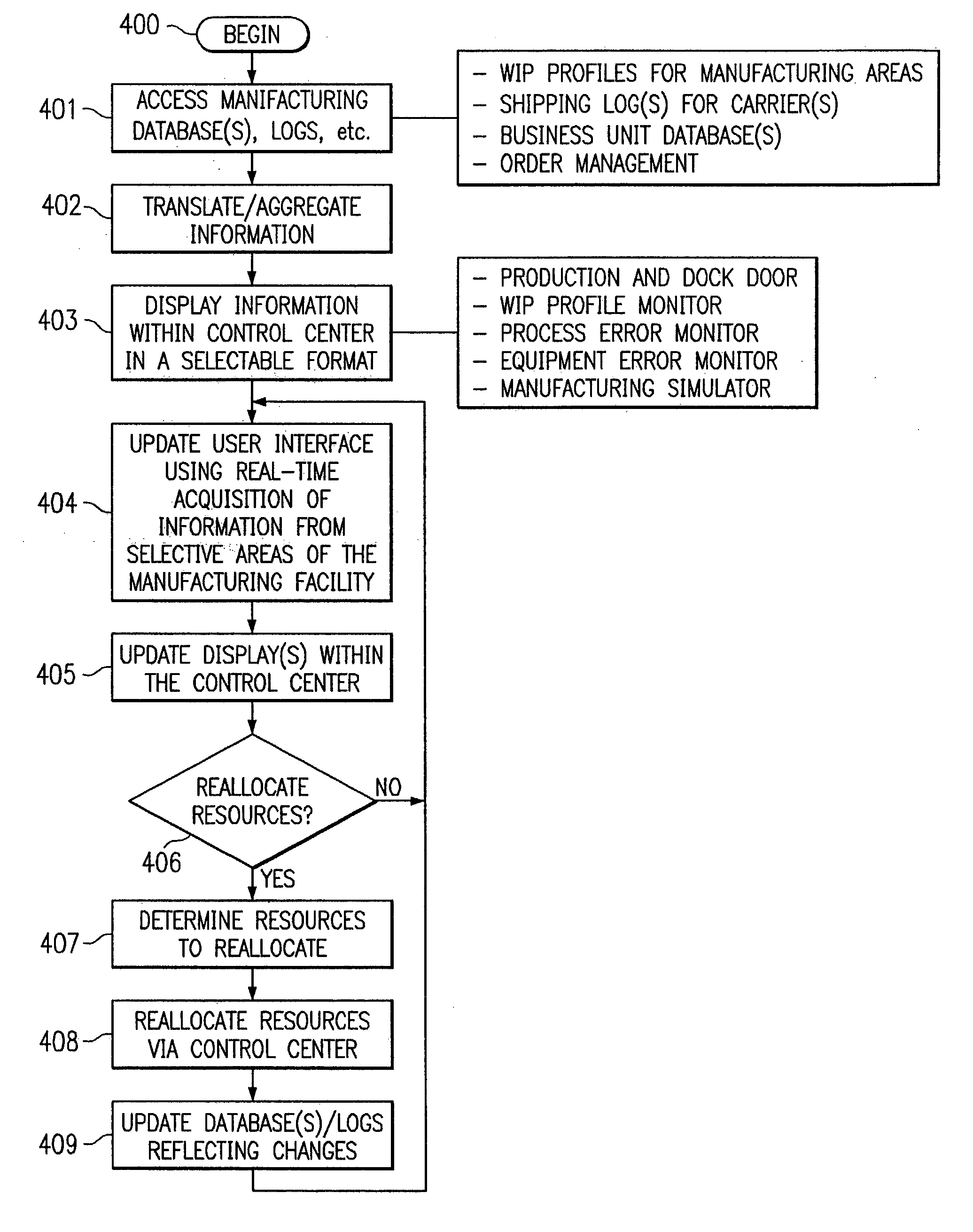
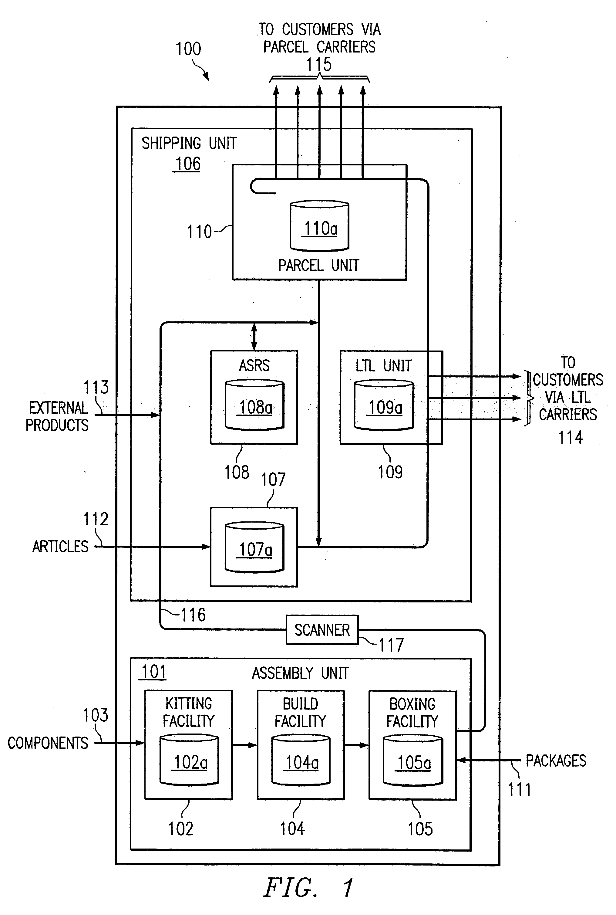
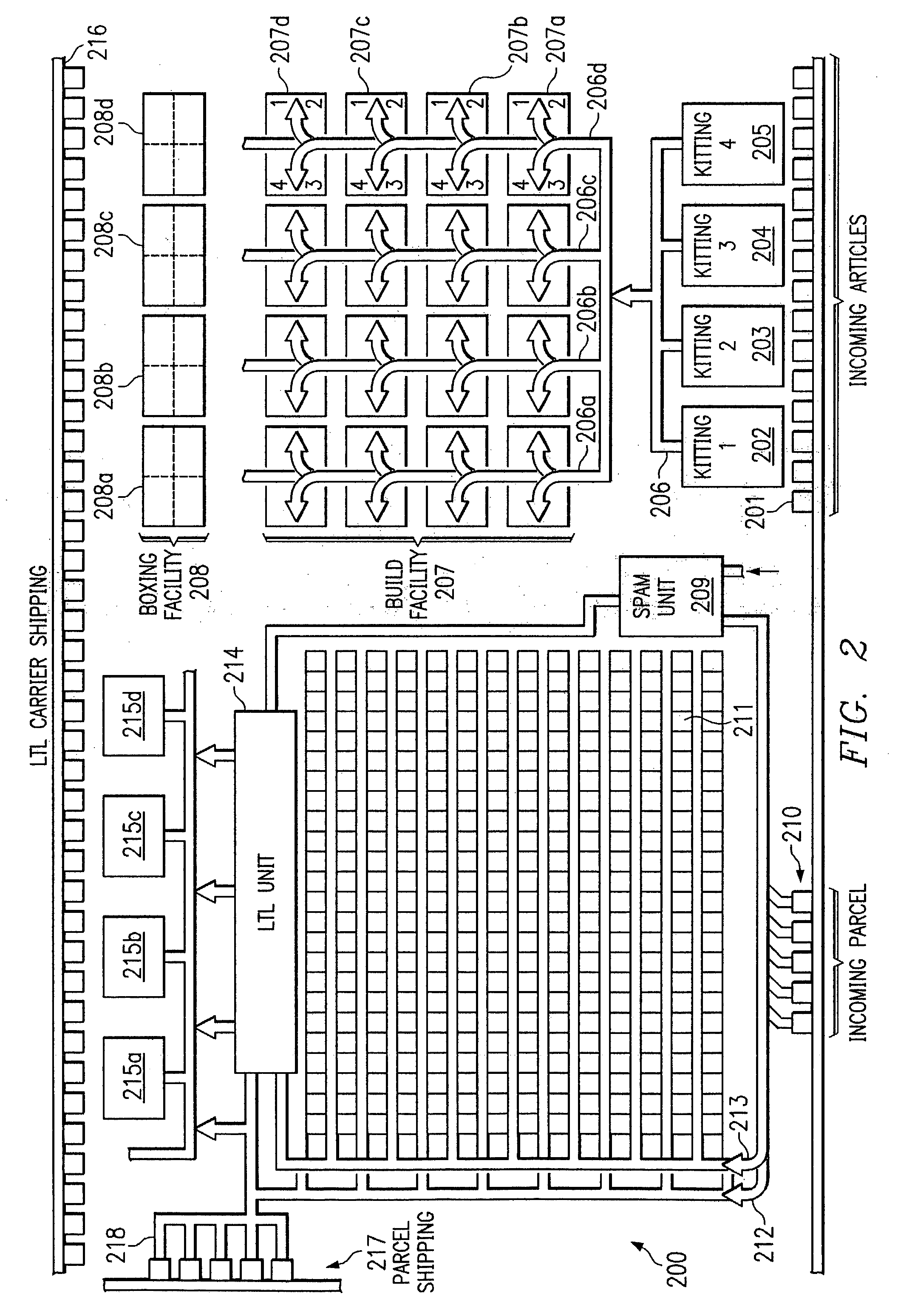
[0022] Preferred embodiments and their advantages are best understood by reference to FIGS. 1 through 6, wherein like numbers are used to indicate like and corresponding parts. Referring to FIG. 1, there is depicted an exemplary manufacturing facility 100 according to the present disclosure. In the illustrative embodiment, manufacturing facility 100 is used to manufacture computers, which are shipped directly to customers, along with associated articles (such as monitors, speakers, printers, etc). Manufacturing facility 100 is operated according to a new process and includes significant architectural enhancements, new hardware, and new control logic that provides increased quality and efficiency.

[0023] During production, the manufacturer receives one or more customer orders from a business unit and orders components from suppliers needed to manufacture the products for those orders and articles and packaging (such as boxes and protective inserts) needed to fill the orders. Preferabl...


PUM


Abstract

A method and system provide for the control of resource allocation within a build-to-order manufacturing environment. One example embodiment of a method according to the present disclosure includes an operation for monitoring a work-in-process (WIP) profile that represents dynamic attributes of an area in a manufacturing facility. A user interface in a control center for the manufacturing facility may be automatically updated to depict one or more of the dynamic attributes in substantially real time, based on one or more of the WIP profiles. After the user interface is updated, user input that specifies a desired reallocation of resources for the manufacturing facility may be received. The user input may trigger communications with one or more areas in the manufacturing facility to implement the desired reallocation of resources. Alternative embodiments may include additional or alternative features, such as features for error detection and recovery.

Description

[0001] This application is a continuation of U.S. Pat. application Ser. No. 09 / 800,046 filed Mar. 5, 2001 entitled Method, System and Facility for Controlling Resource Allocation within a Manufacturing Environment filed by Branden Clark Bickley et al.[0002] The present disclosure generally relates to manufacturing and, more particularly to a method, system and facility for controlling resource allocation within a manufacturing environment.BACKGROUND OF THE DISCLOSURE[0003] Many years ago, manufacturers learned that, when building sufficiently large quantities of identical products, assembly lines could be used to increase the rate of production and decrease the per-unit production costs. In an assembly line, the assembly process is divided in a series of processing steps through which the work-in-process moves to result in the end product. These steps may be optimized, and once the manufacturing system becomes operational it will build a number of products with the same configuratio...

Claims


Application Information

Patent Timeline
15 Jan 2004
Publication
US20040010334A1
IPC
G05B19/418; G06F19/00; G06Q10/06; G06Q20/20
CPC
G05B19/4183; G05B2219/31385; G05B2219/31406; G06Q20/206; G06Q10/06; G06Q10/06312; G05B2219/32181; Y02P90/02
Inventors
BICKLEY, BRANDEN CLARK; PAPE, MARK ALLEN