
Gas separation by combined pressure swing and displacement purge

a gas separation and displacement purge technology, applied in the direction of separation processes, dispersed particle separation, electrochemical generators, etc., can solve the problems of inefficient use of known adsorbent materials for performing adsorption separation, inability to achieve the separation of common relatively less-strongly adsorption-free feed gas components, and limited application of displacement purge processes. , to achieve the effect of low void fraction, low pressure drop and low pressure drop

Inactive Publication Date: 2004-01-22
AIR PROD & CHEM INC
View PDF99 Cites 37 Cited by
  • Summary
  • Abstract
  • Description
  • Claims
  • Application Information

AI Technical Summary

Benefits of technology

[0014] The process for each adsorber includes a feed step in which the first gas mixture is admitted at a first total pressure to a first end of the adsorber, while a first or "light" product gas enriched in component A is delivered from a second end of the adsorber as component B is preferentially adsorbed on the adsorbent contacting the flow channel(s) of the flow path within the adsorber. The process also includes a displacement purge step in which displacement purge gas-containing component C is admitted to one end of the adsorber, while a second gas mixture (or "heavy" product gas) is delivered at a second total pressure from the other end of the adsorbers as component B desorbs from the adsorbent. The first and second pressures may be substantially similar, or the second pressure may be substantially less than the first pressure to obtain a pressure swing component for the separation process. Also, the temperatures of the components may vary, such as component C being at a higher temperature than other components, to obtain a temperature swing component for the separation process. In such cases where the pressure and / or temperature of the first product gas and second gas mixture are varied, such variations may be employed to increase the overall efficiency of the separation process.
[0015] In an aspect where gas components A and C are incompatible, immediately prior to the displacement purge step, a first "buffer" step is performed in the disclosed process, in order to remove interstitial and adsorbed component A accumulated in the adsorber from the previous feed step, so as to avoid contamination of the second gas mixture (containing components B and C) to be produced in the imminent displacement purge step by component A. Likewise, immediately following the displacement purge step, a second "buffer" step is performed in the disclosed process, in order to remove interstitial and adsorbed component C accumulated in the adsorber from the previous purge step, to avoid contamination of the first product gas to be produced in the following feed step by component C.
[0018] The total pressure may be reduced (e.g. below the second pressure at which the displacement purge step is conducted) during the buffer steps to assist the removal of components A or C to be purged, and also to avoid any leakage (external to the adsorbers) of components A or C between process steps preceding and following each buffer step. With reduced total pressure in a first buffer step, desorbing component B may assist the purging of component A during that first buffer step. Hence, a minor pressure swing to reduce the total pressure during buffer steps, by a modest level of vacuum if the second pressure is substantially atmospheric, may be used to enhance the reliability of the buffer steps, independently of whether a larger pressure swing is applied to assist the enrichment of component A. Similarly, a minor temperature swing may be implemented during buffer steps to assist in purging of the relevant component, and to thereby enhance the reliability of the buffer step, or alternatively to enhance the efficiency of the following adsorption or desorption step.
[0024] The rotor of a rotary adsorption module embodiment for use in the disclosed systems and processes includes a plurality of flow paths for receiving adsorbent material therein for preferentially adsorbing a first gas component in the flow paths relative to a second gas component. The gas separation system also may include compression machinery coupled to the rotary module for facilitating gas flow through the flow paths for separating the first gas component from the second gas component. The stator includes a first stator valve surface, a second stator valve surface, and plurality of function compartments opening into the stator valve surfaces. The function compartments include a gas feed compartment, and a light gas component exit compartment, and a buffer gas compartment. "Light gas" refers to withdrawn gas enriched in the second, less readily adsorbed component, which is typically withdrawn from the second ends of adsorbers via the second valve means. However, in some processes according to the present disclosure which are adapted for implementation with the above described rotary module embodiment, feed gas mixture may enter the adsorbent beds at the second end of the adsorbers via the second valve means, and light product gas may be withdrawn at the first end. Similarly, any buffer or purge steps incorporated in such processes may be performed in either direction by admitting buffer or purge gas to either the first or second end of an adsorber. In the case where the disclosed rotary module is operated utilizing a gas separation process including a substantial pressure swing component, in addition to displacement purge, the function compartments may additionally include light reflux exit and return or other compartments to conduct light reflux, blowdown, pressurization or other gas flows related to the pressure swing component of the gas separation process to and from the adsorbers. Any such gas flows, in addition to product, buffer or purge gas flows may also be transferred from one adsorber to another, for flow through the receiving adsorber in either direction, by means of fluid connection means extending between the respective function compartments opening into the first and second stator valve faces. Such inter-adsorber transfer of gas flows may be utilized for example to recycle buffer gas flows between adsorbers to effectively enhance recovery of product gas components (A and B) by capturing product flows expelled from the adsorbers at the onset of a buffer step (instead of exhausting those product flows to the atmosphere), and to reduce the volume of buffer gas required to perform the buffer steps. Additionally, recycling of buffer gas flows expelled at the onset of subsequent feed or purge steps in some embodiments of the presently disclosed processes enables the reduction of residual buffer gas remaining in adsorbers following a buffer step that may be delivered in product gas flows (containing product components A or B), thereby increasing the purity of product gas flows, and reducing any buildup of buffer gas component in cases where product gas components may be recycled through downstream systems or processes.

Problems solved by technology

Previously, application of displacement purge processes has been limited by compatibility of components A, B and C. Even within the context of an overall separation being achieved, some intimate mixing will take place due to axial dispersion in the adsorbers, fluid holdup in gas cavities, and leakage across fluid seals and valves.
Further, the efficient application of known adsorbent materials for performing adsorptive separations utilizing displacement purge-based regeneration techniques has previously been limited due to conventional physical arrangements of the adsorbent material in adsorbers or adsorbent beds, leading to non-optimal separation of some common relatively less-strongly adsorbed feed gas components, particularly when the feed gas also includes another strongly adsorbed component in addition to a desired light product component.
In that application, displacement purge using air (or any oxygen-containing gas with oxygen appearing as a component C) would in the prior art have been impracticable or at least impractical, owing to the hazards of cross-contamination between hydrogen and oxygen.

Method used


Image

  • Gas separation by combined pressure swing and displacement purge
  • Gas separation by combined pressure swing and displacement purge
  • Gas separation by combined pressure swing and displacement purge

Examples


Embodiment Construction

[0037] FIGS. 1-4

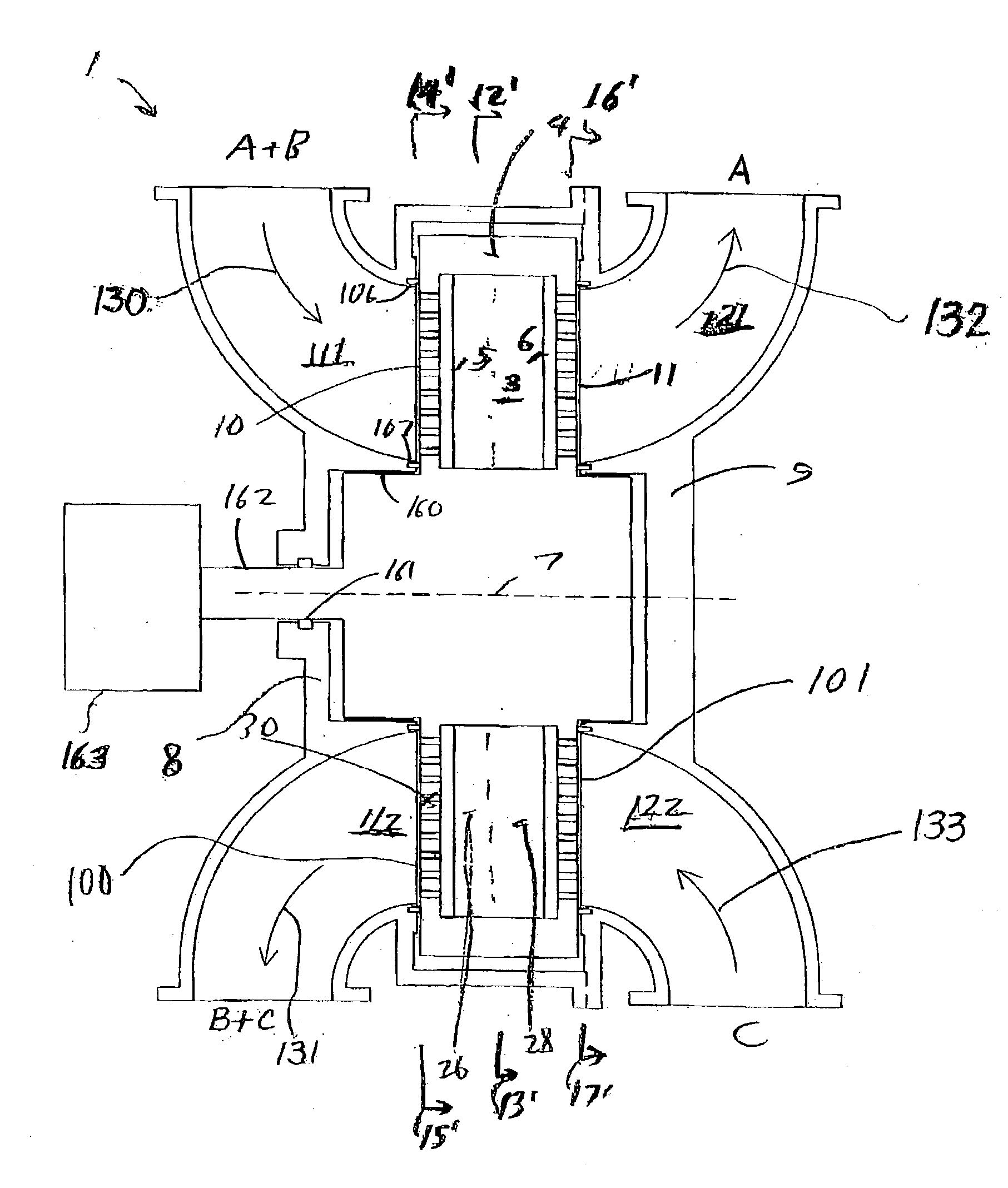
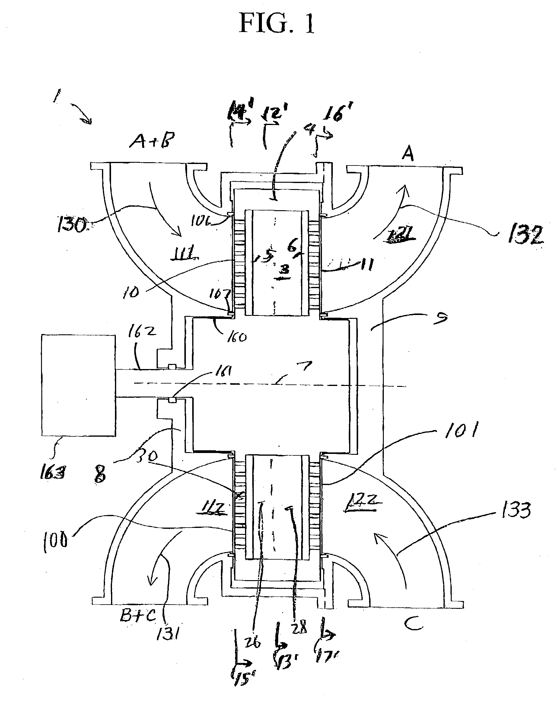
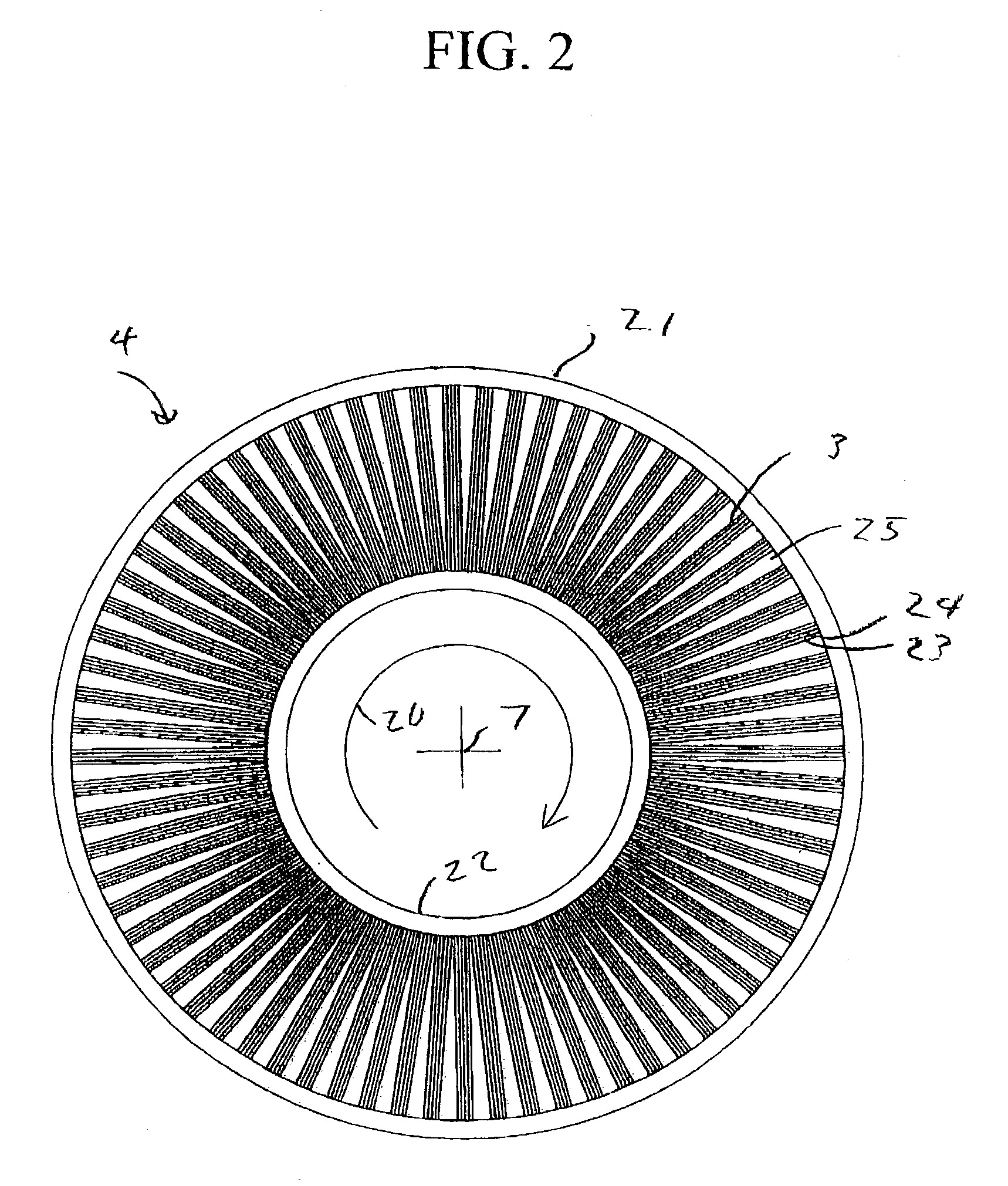
[0038] A rotary adsorption module with displacement purge regeneration is described below in connection with FIGS. 1-4. As used herein, a "rotary adsorption module" includes, but is not limited to, either a device wherein an array of adsorbers rotates relative to a fixed valve face or stator or a device wherein the valve face or stator rotates relative to an array of adsorbers. Illustrated embodiments have the adsorbers mounted in a rotor, with the rotor in a housing, which is a stator with fixed valve faces.

[0039] FIG. 1 shows a rotary adsorption module 1, which includes a number "N" (where N is an integer number equal to or greater than 2) of adsorbers 3 or adsorber channels 3 in adsorber housing body 4. Each adsorber has a first end 5 and a second end 6, with a flow path therebetween contacting an adsorbent material over which a gas component B is more readily adsorbed relative to a component A and a component C which are less readily adsorbed. The adsorbers are d...


PUM


Abstract

The present disclosure relates to systems and processes for adsorptive gas separations where a first gas mixture including components A and B is to be separated so that a first product of the separation is enriched in component A, while component B is mixed with a third gas component C contained in a displacement purge stream to form a second gas mixture including components B and C, and with provision to prevent cross contamination of component C into the first product containing component A, or of component A into the second gas mixture containing component C. The invention may be applied to hydrogen (component A) enrichment from syngas mixtures, where dilute carbon dioxide (component B) is to be rejected such as directly to the atmosphere, and with preferably nitrogen-enriched air as the displacement purge stream containing residual oxygen (component C).

Description

[0001] The present application claims the benefit of the earlier filing date of applicants' copending U.S. provisional application No. 60 / 364,772, filed Mar. 14, 2002, which is incorporated herein by reference.FIELD[0002] This application is related to adsorptive gas separation apparatus and systems, particularly rotary adsorptive gas separation apparatus and systems, as well as fuel cell applications, and QuestAir Technologies' related patents and patent applications, including U.S. Pat. Nos. 6,406,523, 09 / 808,715, 10 / 039,940, and 60 / 351,798, the disclosures of which are incorporated herein by reference.[0003] For enriching a component A of a feed gas mixture containing components A and B, an adsorbent material over which component B is more readily adsorbed and component A is less readily adsorbed may be provided, as is disclosed in the prior art. The adsorbent material is typically arranged to contact flow channels in adsorbers or adsorbent beds. When the gas mixture is introduce...

Claims


Application Information

Patent Timeline
IPC IPC(8): B01D53/04B01D53/047B01D53/06H01M8/06
CPCB01D53/0431B01D53/0462B01D53/047B01D53/06Y02C10/08B01D2257/504B01D2259/40043B01D2259/40056B01D2256/16Y02C20/40
Inventor KEEFER, BOWIE G.BABICKI, MATTHEW L.BOULET, ANDRE JASON JOSEPHPELMAN, AARON M.SELLARS, BRIAN G.ROY, SURAJIT
Owner AIR PROD & CHEM INC
Learn More