Permanent magnet and method for preparation thereof
Inactive Publication Date: 2004-02-12
SUMITOMO SPECIAL METAL CO LTD
View PDF4 Cites 1 Cited by
Summary
Abstract
Description
Claims
Application Information
AI Technical Summary
This helps you quickly interpret patents by identifying the three key elements:
Problems solved by technology
Method used
Benefits of technology
Benefits of technology
[0108] It should be noted that even though the charge compensation is not the issue, the respective substituents still need to be added at the best ratio because the magnetic properties might deteriorate depending on the ratios defined for those elements. Thus, according to the present invention, the respective substituents are added in predetermined amounts and the manufacturing process, composition and additives are optimized to add them at the best ratio. In this manner, the present inventors improved the magnetic properties successfully.
[0112] When Sr is selected as the element A, the magnetic properties are improved more significantly than the situation where Ba, Pb or Ca is selected as the element A. For that reason, Sr is preferably selected as the element A as an indispensable component. Depending on the specific application, however, it may be more advantageous to select Ba, for example, to reduce the cost.
[0131] If necessary, a boron compound (such as B.sub.2O.sub.3 or H.sub.3B.sub.O.sub.3) may be added to the powder. Also, a sulfate of at least one element, which is selected from the group consisting of Sr, Ba, Pb, Ca, Y, the rare earth elements, Bi and Fe, may be used as a portion of the material powder. By using any of these additives, the reactivity to the ferrite phase with the M-type magnetoplumbite structure during the calcining process can be improved and the grain growth can be minimized, thus improving the magnetic properties. These effects are achieved particularly noticeably when the Formula 1 satisfies n>6, in which range it was believed that no single-phase ferrite with the M-type magnetoplumbite structure could be obtained and no good magnetic properties should be achievable.
[0148] The spray solution may be calcined with a hydrochloric acid collector at an ironworks. Then, a calcined body can be obtained efficiently by the spray pyrolysis process.
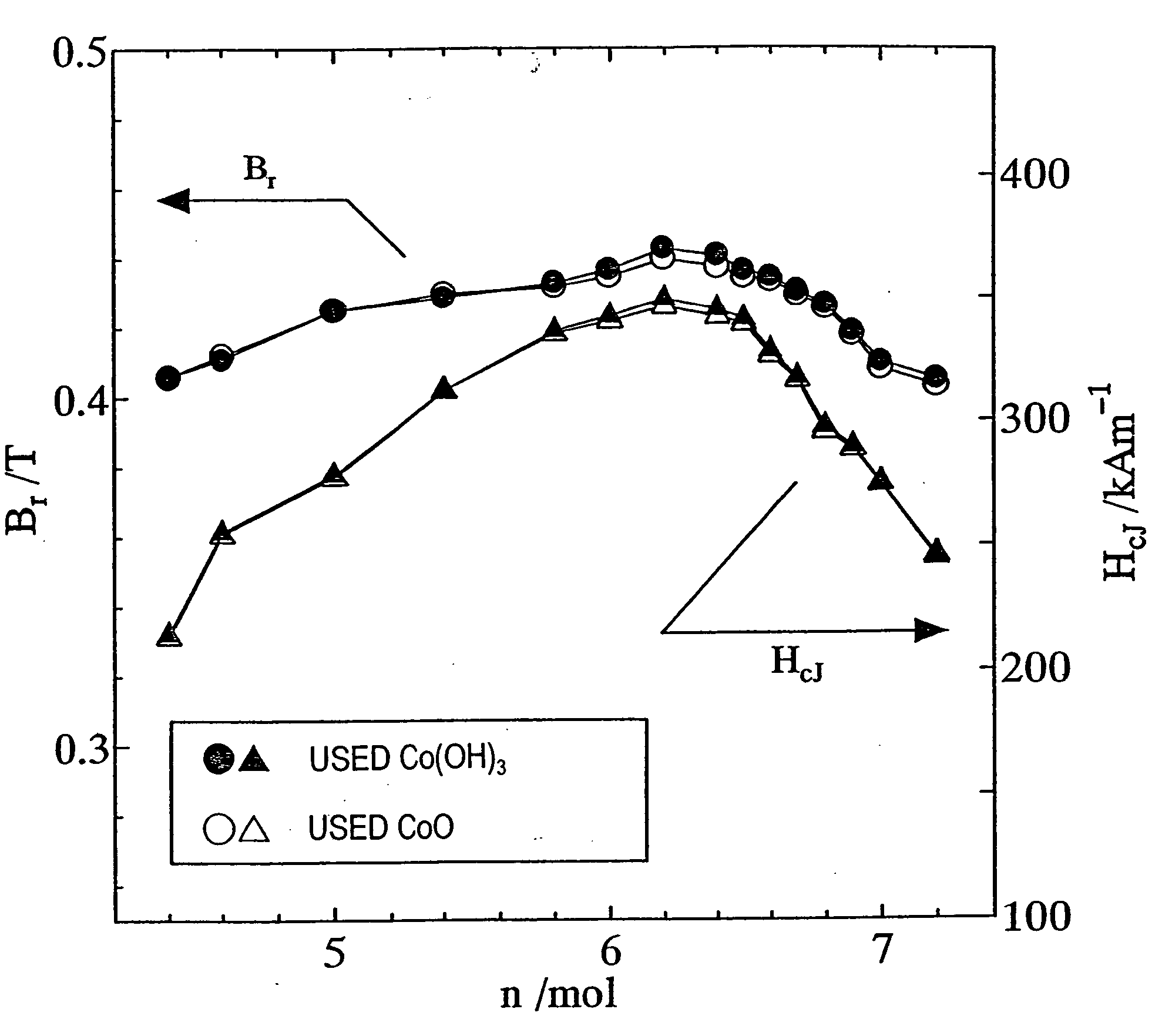
[0151] The oxide of Mn or the oxide of Co described above may be partially or fully replaced with a hydroxide of Mn or a hydroxide of Co. Some of these hydroxides are believed to be hydrated oxides or oxidized hydroxides of Mn or Co. As for Co, for example, cobalt hydroxides such as Co(OH).sub.2 and / or Co(OH).sub.3 may be used as hydroxides of Co. It should be noted that Co(OH).sub.3 is believed to be a hydrated oxide of Co. Particularly when a cobalthydroxide is used, the magnetic properties can be improved significantly. These effects are achieved particularly noticeably when the Formula 1 satisfies n>6, in which range it was believed that no single-phase ferrite with the M-type magnetoplumbite structure could be obtained and no good magnetic properties should be achievable.
[0165] A method for producing a ferrite magnet according to the present invention is characterized by preparing a ferrite having a substantially M-type magnetoplumbite structure and represented by (1-x)AO.(x / 2)R.sub.2O.sub.3.nFe.sub.2O.sub.3 (where A is at least one element selected from the group consisting of Sr, Ba, Pb and Ca and R is at least one element selected from the group consisting of the rare earth elements (including Y) and Bi and always includes La) and then adding either an oxide of Mn or oxides of Mn and Co thereto during a fine pulverization process. Thus, even if the ferrite having the M-type magnetoplumbite structure is a mother material with a constant composition, a ferrite magnet, exhibiting any desired combination of magnetic properties that fall somewhere within a broad range, can be easily obtained by appropriately changing the amounts of the additives during the fine pulverization process. Thus, the present invention is very effectively applicable for use in a manufacturing process of producing ferrite magnets with a wide variety of magnetic properties.
Problems solved by technology
However, none of these ferrite magnets can improve the magnetic properties sufficiently and reduce the manufacturing cost significantly at the same time.
However, the properties of such a ferrite are still not fully satisfactory.
But if a rare earth element (such as La) and Co are used in large amounts as substituents for a ferrite, then the material cost of such a ferrite increases adversely because the raw materials of these substituents are expensive.
In that case, the essential feature of the ferrite magnet, which should be produced at a lower manufacturing cost than a rare earth magnet, for example, might be lost.
Method used
Image
Click on the blue label to locate the original text in one second.
Reading with bidirectional positioning of images and text.
Examples
example 2
[0174] First, as in the first example described above, a calcined body magnet powder with a composition (1-x)SrO.(x / 2)La.sub.2O.sub.3.nFe.sub.2O-.sub.3 was prepared so as to satisfy x=0.2 and n=6.0.
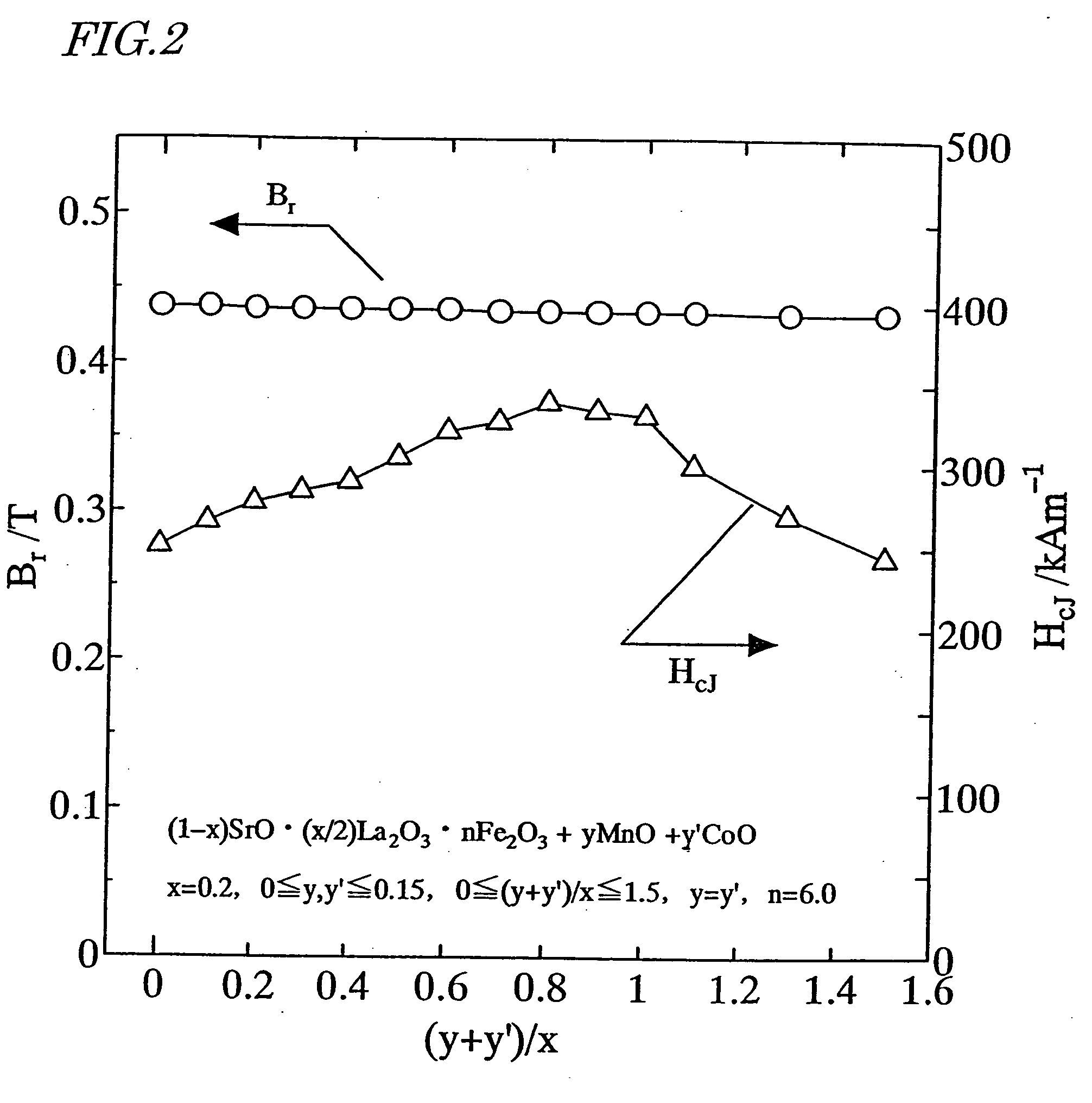
[0175] Next, an Mn.sub.3O.sub.4 powder and a CoO powder were added to the calcined body magnet powder so as to satisfy 0.ltoreq.y.ltoreq.0.15, 0.ltoreq.y'.ltoreq.0.15, 0.ltoreq.(y+y') / x.ltoreq.1.5 and y=y', where y and y' are mole fractions of Mn and Co to be added to one mole of the calcined body magnet powder. Thereafter, the same process steps as those of the first example were carried out to prepare a sintered body.
[0176] The remanence B.sub.r and coercivity H.sub.cJ of the resultant sintered magnet were measured. The results of measurement are shown in FIG. 2. As can be clearly seen from FIG. 2, the remanence B.sub.r and coercivity H.sub.cJ both increased when 0.2.ltoreq.(y+y') / x.ltoreq.0.8.
example 3
[0177] First, as in the first example described above, a calcined body magnet powder with a composition (1-x)SrO.(x / 2)La.sub.2O.sub.3.nFe.sub.2O-.sub.3 was prepared so as to satisfy x=0.2 and 4.4.ltoreq.n.ltoreq.7.2.
[0178] Next, an Mn.sub.3O.sub.4 powder and a CoO powder were added to the calcined body magnet powder. Thereafter, the same process steps as those of the first example were carried out to prepare a sintered body. The amounts of the powders added were adjusted in such a manner as to satisfy y=0.08, y'=0.08 and (y+y') / x=0.8, where y and y' are mole fractions of Mn and Co to be added to one mole of the calcined body magnet powder.
[0179] The remanence B.sub.r and coercivity H.sub.cJ of the resultant sintered magnet were measured. The results of measurement are shown in FIG. 3. As can be clearly seen from FIG. 3, the remanence .sub.B and coercivity H.sub.cJ both increased when 5.0.ltoreq.n.ltoreq.6.7.
example 4
[0180] First, as in the first example described above, a calcined body magnet powder with a composition (1-x)SrO.(x / 2)La.sub.2O.sub.3.nFe.sub.2O-.sub.3 was prepared so as to satisfy x=0.2 and n=6.0.
[0181] Next, an Mn.sub.3O.sub.4 powder and a CoO powder were added to the calcined body magnet powder. Thereafter, the same process steps as those of the first example were carried out to prepare a sintered body. The amounts of the powders added were adjusted in such a manner as to satisfy y=0.20 and y'=0 (Sample No. 1), y=0.15 and y'=0.05 (Sample No. 2) and y=0.10 and y'=0.10 (Sample No. 3), where y and y' are mole fractions of Mn and Co to be added to one mole of the calcined body magnet powder. Meanwhile, samples to which no Mn.sub.3O.sub.4 or CoO was added were also prepared as comparative examples Nos. 1 and 2.
[0182] The remanence B.sub.r and coercivity H.sub.cJ of the resultant sintered magnet were measured. The results of measurement are shown in the following Table 1. As can be cl...
PUM
Property
Measurement
Unit
Angle
aaaaa
aaaaa
Angle
aaaaa
aaaaa
Angle
aaaaa
aaaaa
Abstract
A ferrite magnet obtained by adding either an oxide of Mn or oxides of Mn and Co to a ferrite having a hexagonal M-type magnetoplumbite structure, in which a portion of Sr, Ba, Pb or Ca is replaced with at least one element that is selected from the group consisting of the rare earth elements (including Y) and Bi and that always includes La, during the fine pulverization process thereof, and then subjecting the mixture to re-calcining and / or sintering process(es). By adding a small amount of the element Mn or elements Mn and Co to the ferrite already having the hexagonal M-type magnetoplumbite structure during the fine pulverization process thereof, the magnetic properties can be improved.
Description
[0001] The present invention relates to a ferrite magnetpowder, a magnet made of the magnetpowder, and methods of making the magnetpowder and the magnet.[0002] Ferrite is a generic term for any compound including an oxide of a divalent cationic metal and trivalent iron, and ferrite magnets have found a wide variety of applications in numerous types of rotating machines, loudspeakers, and so on. Typical materials for a ferrite magnet include Sr ferrites (SrFe.sub.12O.sub.19) and Ba ferrites (BaFe.sub.12O.sub.19) having a hexagonal magnetoplumbite structure. Each of these ferrites is made of iron oxide and a carbonate of strontium (Sr), barium (Ba) or any other suitable element, and can be produced at a relatively low cost by a powder metallurgical process.[0003] A basic composition of an (M-type) ferrite having the magnetoplumbite structure is normally represented by the chemical formula AO.6Fe.sub.2O.sub.3, where A is a metal element to be divalent cations and is selected from th...
Claims
Application Information
Patent Timeline
Application Date:The date an application was filed.
Publication Date:The date a patent or application was officially published.
First Publication Date:The earliest publication date of a patent with the same application number.
Issue Date:Publication date of the patent grant document.
PCT Entry Date:The Entry date of PCT National Phase.
Estimated Expiry Date:The statutory expiry date of a patent right according to the Patent Law, and it is the longest term of protection that the patent right can achieve without the termination of the patent right due to other reasons(Term extension factor has been taken into account ).
Invalid Date:Actual expiry date is based on effective date or publication date of legal transaction data of invalid patent.

