Magnetic reproducing apparatus and magnetic reproducing method

a reproducing apparatus and magnetic technology, applied in the field of magnetic reproducing apparatus, can solve the problems of reducing the amount of reduction, the linearity of the recording track pattern, and the state in which the reproducing trace tp laps over the adjacent recording track tr2 unavoidably, so as to eliminate the effects of crosstalk signal and eliminate the effect of crosstalk signal

Inactive Publication Date: 2004-03-04
SONY CORP
View PDF6 Cites 0 Cited by
  • Summary
  • Abstract
  • Description
  • Claims
  • Application Information

AI Technical Summary

Benefits of technology

0020] Further, according to claim 8 of the present invention, since a Partial Response Class 4 is employed as a detecting method, a detecting method in which low-frequency components of a reproduction signal are not used is obtained to eliminate effects of a crosstalk signal caused by the fact that a reproduction trace laps over adjacent recording tracks.
0021] Further, according to claim 9 of the present invention, since an E-Partial Response Class 4 is employed as a detecting method, a detecting method in which low-frequency components of a reproduction signal are not used is obtained to eliminate effects of a crosstalk signal caused by the fact that a reproduction trace laps over adjacent recording tracks.
0022] Further, according to claim 10 of the present invention, since an EE-Partial Response Class 4 is employed as a detecting method, a detecting met

Problems solved by technology

However, in the recording according to the above-described helical scanning method, there is a limit in the linearity of the recording track pattern when the track pitch is made narrower.
Moreover, when the track pitch is made narrower beyond the limit of linearity as described above, since the recording track Tr is not corresponding to the reproduction trace Tp, a state in which the reproduction trace Tp laps over the adjacent recording track Tr2 unavoidably occurs.
However, as shown in frequency characteristics of FIG. 17, the amount of reduction, that is, azimuth loss can not be anticipated especially in the low-frequency area.
Although reproduc

Method used


Image

  • Magnetic reproducing apparatus and magnetic reproducing method
  • Magnetic reproducing apparatus and magnetic reproducing method
  • Magnetic reproducing apparatus and magnetic reproducing method

Examples


Embodiment Construction

[0042] In the present invention, a detecting method in which low-frequency components of a reproduction signal are not used is employed as reproduction means for reproduction according to a non-tracking method, and thus effects of a crosstalk signal caused by the fact that a reproduction trace laps over adjacent recording tracks may be eliminated, whereby a reproduction according to the non-tracking method can be adopted to enable the width of a recording track to be made narrower, and to improve the recording density of a magnetic tape.

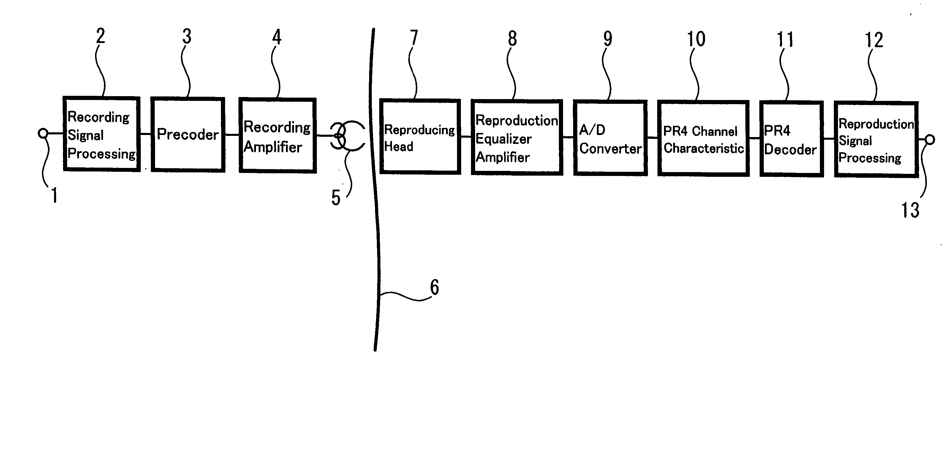
[0043] Referring to drawings, hereinafter the present invention will be explained, and FIG. 1 is a block diagram showing an embodiment of a data magnetic recording and reproducing apparatus to which a magnetic reproducing apparatus according to the present invention is applied.

[0044] In FIG. 1, video data, audio data, additional data, data in files of a computer and the like are input to a data input 1. A signal input from the data input 1 is process...


PUM


Abstract

There are provided a magnetic reproducing apparatus and a magnetic reproducing method, which are suitable for use in reproducing a magnetic tape by using, for example, a magnetoresistive element. A signal input from a data input 1 undergoes processing suitable for magnetic recording in a recording signal processing circuit 2, and is supplied to a predetermined precoder 3. The signal from the precoder 3 is recorded by a recording head 5 on a recording medium 6 such as a magnetic tape through a recording amplifier 4. The signal read from the recording medium 6 by the reproducing head 7 is supplied to a reproduction equalizer amplifier 8 to be amplified and equalized. The equalized signal is supplied to a circuit 10 having a channel characteristic of, for example, a Partial Response Class 4 (PR4) through an A/D converter 9. The output signal from the circuit 10 is supplied to a PR4 decoder circuit 11 to detect the signal. Further, the signal from the decoder circuit 11 is sent to a reproduction signal processing circuit 12. Then, the signal is output to a data output 13 after executing demodulation, restoration to the original form from the packetized state of the signal, error correction and the like. Accordingly, the magnetoresistive element conventionally used for reproducing a hard disk and the like may be applied to reproduction of a magnetic tape.

Description

[0001] The present invention relates to a magnetic reproducing apparatus and a magnetic reproducing method, in which a magnetoresistive element which has been conventionally used for reproducing a hard disk and the like, may be applied, for example, to reproducing a magnetic tape, and more particularly, relates to a magnetic reproducing apparatus and a magnetic reproducing method suitable for use in reproduction of a magnetic tape employing the magnetoresistive element.[0002] FIG. 11 shows a block diagram of a data magnetic recording and reproducing apparatus as one example of a magnetic reproducing apparatus. In FIG. 11, video data, audio data, additional data, data in files of a computer and the like are input to a data input 80. A signal input from the data input 80 is processed by a recording signal processing circuit 81 into a signal suitable for magnetic recording, that is, undergoes processing of error correction and packetization, and after modulation the signal is recorded ...

Claims


Application Information

Patent Timeline
IPC IPC(8): G11B5/39G11B5/00G11B5/008G11B5/02G11B5/035G11B5/09G11B5/48G11B20/00G11B20/10G11B20/18
CPCG11B5/00G11B2220/2562G11B5/0086G11B5/02G11B5/035G11B5/09G11B5/488G11B20/00086G11B20/10009G11B20/10055G11B20/10175G11B20/18G11B2005/0016G11B2020/1461G11B5/00813
Inventor KOTANI, YASUTAKAYANAGI, YUJI
Owner SONY CORP
Why Eureka
Try Eureka