Exciter apparatus

a technology of exciter and apparatus, applied in the field of exciter apparatus, can solve problems such as the movement of the centre of gravity

Inactive Publication Date: 2004-03-11
F L SMIDTH & CO AS
View PDF9 Cites 31 Cited by
  • Summary
  • Abstract
  • Description
  • Claims
  • Application Information

AI Technical Summary

Problems solved by technology

However, as the screening apparatus wears, or panels are changed for a different brand, or the machine is loaded with a mass of material and progressively shifts this mass, the centre of gravity moves relative to the direction of vibration.

Method used


Image

  • Exciter apparatus
  • Exciter apparatus
  • Exciter apparatus

Examples


Embodiment Construction

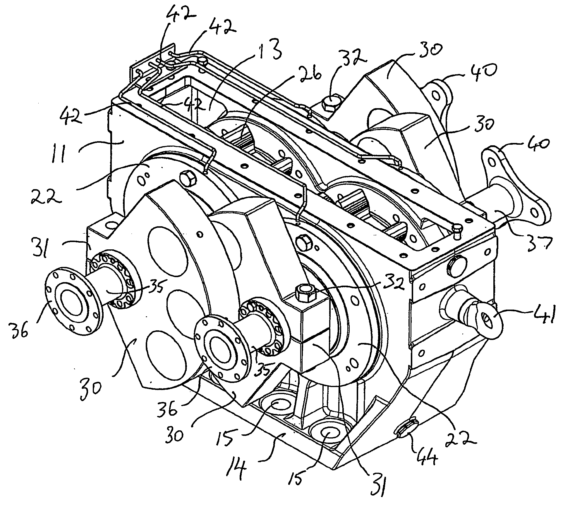
[0008] The exciter assembly may comprise the type having a pair of shafts having corresponding drive means associated respectively with the shafts whereby the rotation of the respective masses may be synchronous. For example, there may be provided a gear arrangement on the respective shafts whereby the masses are maintained substantially synchronous in phase and speed. The synchronization means may be adapted to establish a predetermined velocity and phase relationship between the rotating eccentric masses and to allow effectively independent rotation thereof when the predetermined velocity and phase relationship is achieved.

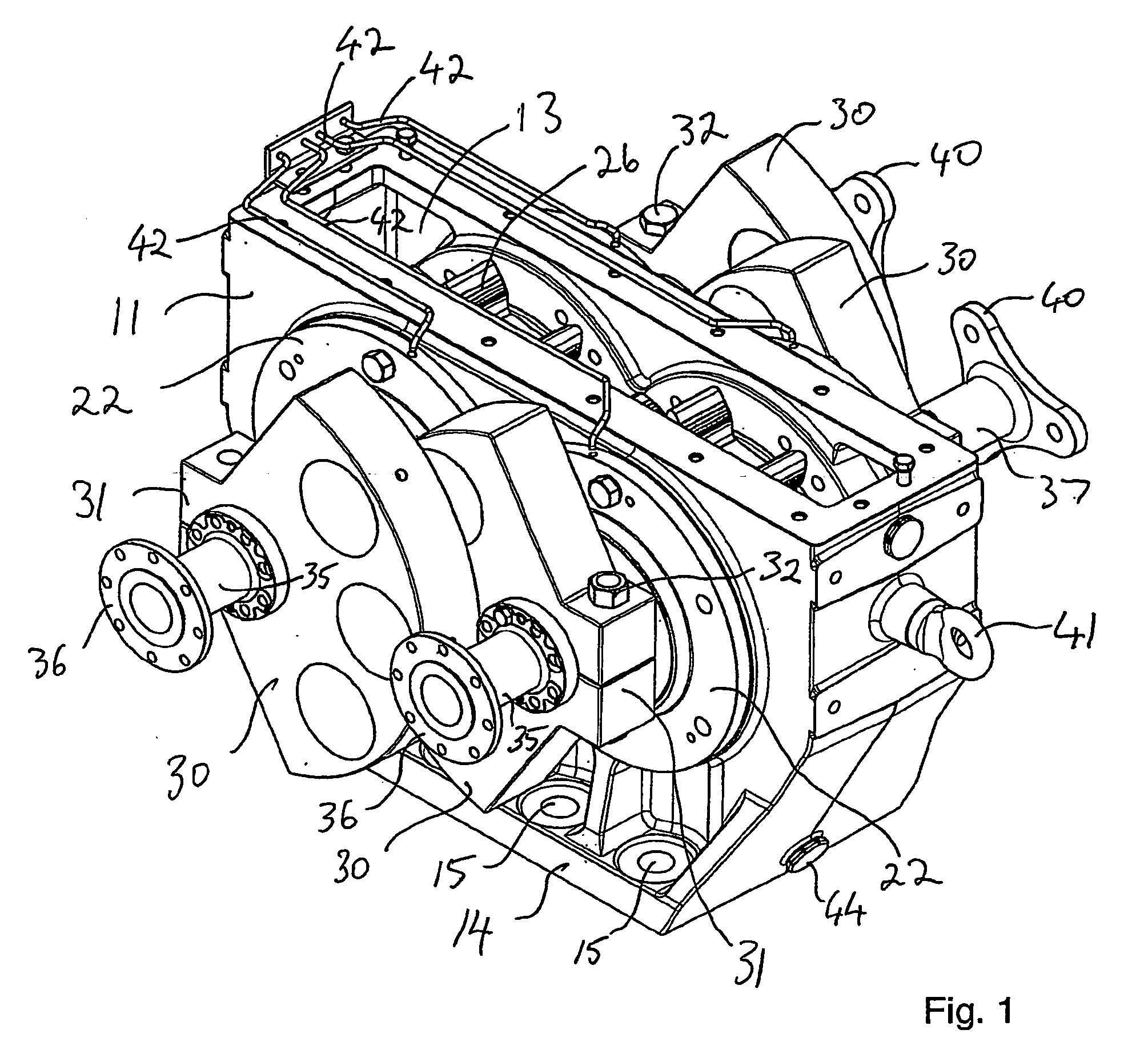
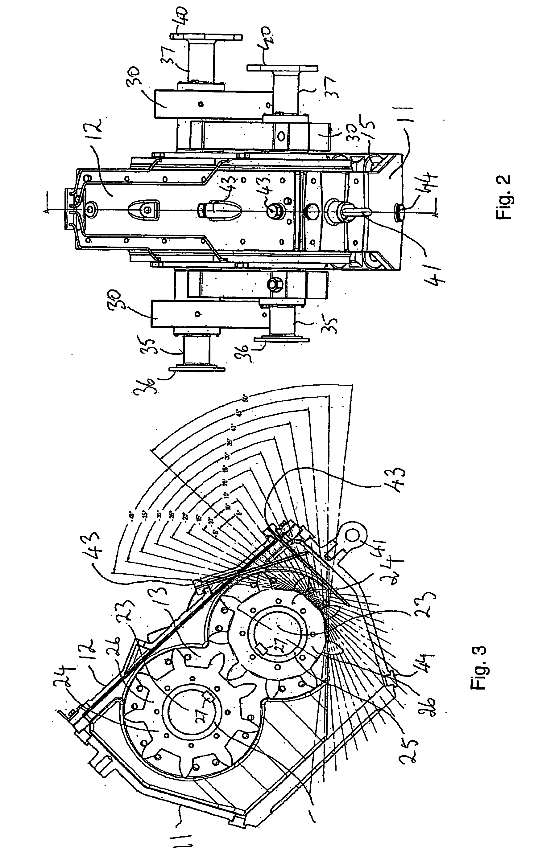
[0009] It is recognized that the median direction of excitation is preferably provided whereby a line in that direction from the inertial divisor of the respective masses passes through the notional centre of gravity of the screen machine. The present applicant has determined that surprisingly as the centre of gravity of the machine shifts away from notional cen...


PUM


Abstract

There is provided exciter apparatus having a cast housing (11) and mounting base (14) secured to mounts bolted to the side plates of screening apparatus. A pair of shafts are mounted for rotation in and extend out of both sides of the cast housing (11). A gear assembly is keyed to each shaft t form a gear train coupling the shafts. The outer ends of each of the shafts are provided with eccentric masses (30) aligned on their respective shafts 180° out of phase. Drive spools (35) are driven by electric motors (not shown). Coupling spools (37) are adapted to accept flexible couplings for joining exciter units together. The gears (26) comprise 9 teeth of an 18-tooth module at 325.0 mm pitch circle diameter (PCD) and 65 mm axial dimension. The lands between the teeth are at a notional diameter 262.6 mm, the teeth having a corresponding notional tooth height of 31.2 mm to the PCD. The gear tooth chordal length at 34 mm is oversize for the module and the gear tooth involute surface extends past the gear tooth addendum to meet a 6.5 mm radius tooth tip. This configuration gives a lash of 9°, which enables the direction of excitation to shift to track the centre of gravity of the screen machine in use.

Description

[0001] This invention relates to exciter apparatus.[0002] This invention relates particularly to exciter apparatus for use in minerals processing vibratory screens, and for illustrative purposes the invention is described hereinafter with reference to this application. However, it is to be understood that the principles underlying the present invention may be applied in other applications such as vibratory screening generally including grading nuts and other food processing applications.[0003] Vibrating screen machines for use in the mineral processing industries are commonly used to separate minerals such as coal or ores by size, usually after crushing. The apparatus generally comprises a screening deck having RHS or boxed I-beam screen support members, the screen support members being spaced apart to support the ends of modular screen inserts rigidly between side plates that are further interconnected by other cross members. The screen deck may be flat or may be curved to form a s...

Claims


Application Information

Patent Timeline
Patent Type & Authority Applications(United States)
IPC IPC(8): B06B1/16B07B1/28B07B1/42
CPCB06B1/166Y10T74/18552B07B1/42B07B1/284
Inventor RUBIE, PETERRUSSELL, JOHNDALZIEL, PAULPLANT, BEN
Owner F L SMIDTH & CO AS
Why Eureka
Try Eureka