Microchannel fabrication

a microchannel and fabrication technology, applied in the direction of hollow wall objects, hollow wall components, instruments, etc., can solve the problems of molten polymer at the entrance of the microstructure, the problem of affecting the quality of the microstructure, and the relatively slow rate of production,

Inactive Publication Date: 2004-03-11
KIM BYUNG +1
View PDF0 Cites 31 Cited by
  • Summary
  • Abstract
  • Description
  • Claims
  • Application Information

AI Technical Summary

Problems solved by technology

The drawback of these silicon-based methods, however, is their relatively slow rate and costly production.
The primary difficulty in molding microstructures is that the molten polymer at the entrance of microstructures will instantaneously freeze upon contacting

Method used


Image

  • Microchannel fabrication
  • Microchannel fabrication
  • Microchannel fabrication

Examples


Embodiment Construction

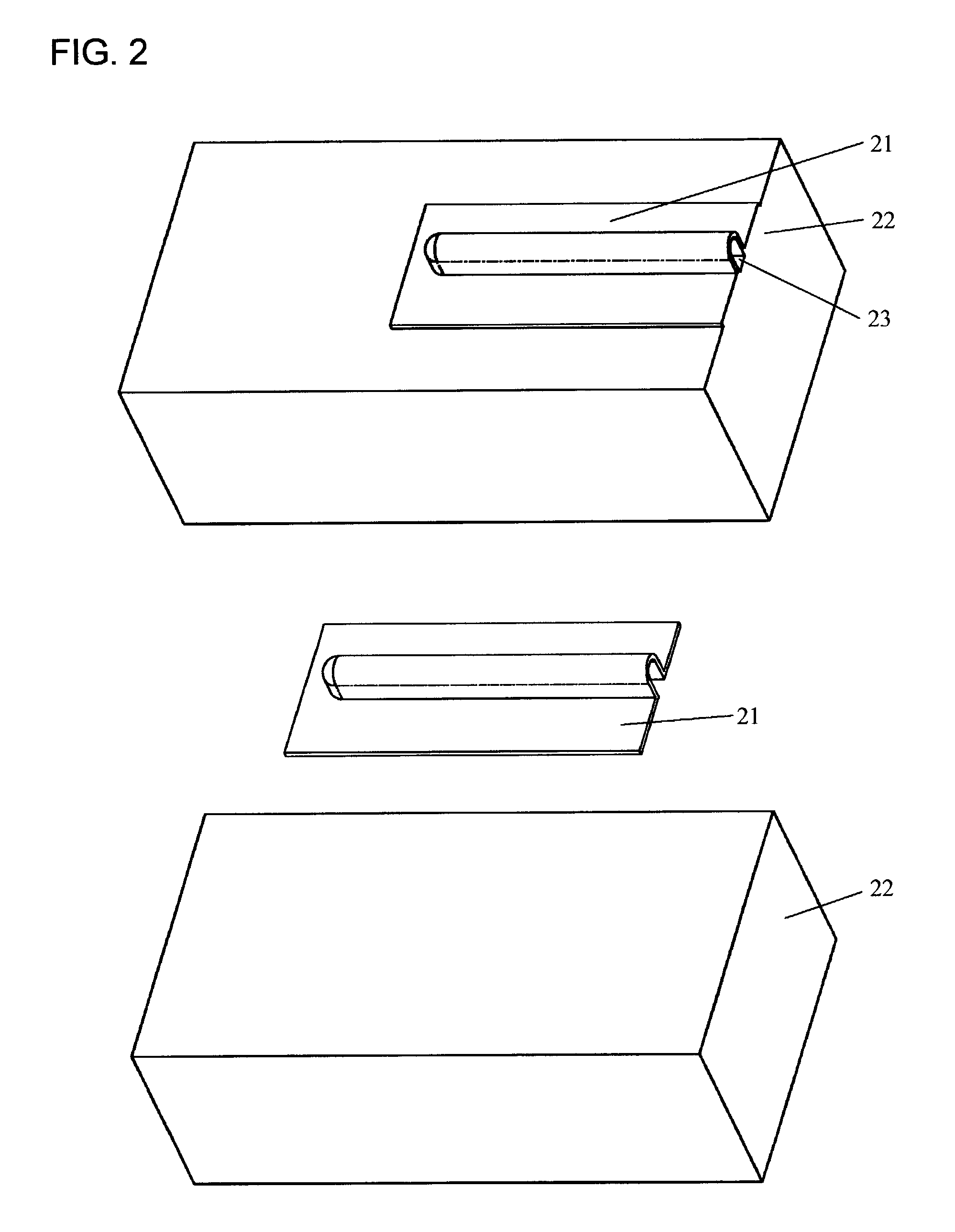
[0030] FIG. 2 shows the design of a straight closed microchannel. The straight closed microchannel 23 is formed between a plastic film 21 and a relatively thick substrate 22. The preferable material for 22 is thermoplastic.

[0031] FIG. 3 shows the design of a U-shape closed microchannel. The U-shape closed microchannel 27 is formed between a plastic film 26 and substrate 22.

[0032] In the same way, more complicated closed microchannels can be designed. The thin thermoplastic film has thickness from a micron to a fraction of a millimeter. It has microchannels on the substrate side, thus forming closed microchannels between the film and the substrate. The layout of microchannels is designed according to actual microfluidic applications. The surface of the substrate is not necessarily flat and general contours can be used by mating the film with the substrate. The shape of the cross section of microchannels can be trapezoidal, rectangular, semicircular, or any other shapes. Microchannels...


PUM

PropertyMeasurementUnit
Lengthaaaaaaaaaa
Temperatureaaaaaaaaaa
Timeaaaaaaaaaa

Abstract

A design of microchannels and a method for economic production of such microchannels. The new microchannel design comprises a thin thermoplastic film and a relatively thick substrate to form microchannels in-between. The microchannels are displaced on the film side. The method for fabricating such microchannels is a hybrid process combining compression, and blowing or vacuum forming to form microchannels between the film and the substrate. During the process, the film is placed on the top of the substrate. A mold or die with to-be-replicated microchannels clamps the film against the substrate. Either blow molding or vacuum forming is then carried out to deform the film and replicate the microchannels. Rapid heatable and coolable molds are preferred to soften the film and form bonds between the film and the substrate while short cycle time is maintained.

Description

[0002] This invention relates in part to the pending application entitled "Method and Apparatus for Rapid Mold Heating and Cooling," with inventors Byung Kim and Donggang Yao, filed on Sep. 4, 2002.[0003] 1. Field of Invention[0004] The field of the invention pertains to microstructure fabrication using thermoplastic materials, and in particular provides a new micromolding method for rapidly fabricating microchannels using thermoplastics.[0005] In the description of the invention, microchannels are defined as channels with characteristic lateral dimension fallen between a tens of one micron to several millimeters. A thermoplastic material is defined as a material which softens upon heating and hardens again upon cooling, such as thermoplastic polymers.[0006] 2. Description of Prior Art[0007] Microchannels are desired in many miniaturized devices. Particularly in biomedical applications, microchannels are used as delivering / branching / sorting systems for immunodiagnostics, genomics, d...

Claims


Application Information

Patent Timeline
IPC IPC(8): B29C35/08B29C35/16B29C51/10B29C51/42B29C65/18B81B1/00
CPCB29C35/08B81C2203/036B29C51/427B29C65/18B29C66/47B29C2035/0822B29C2035/1616B29C2049/4638B29C2791/001B29C2791/006B29C2791/007B29L2024/00B29L2031/756B81B2201/058B81C1/00071B81C1/0046B81C99/0085B29C51/10
Inventor KIM, BYUNGYAO, DONGGANG
Owner KIM BYUNG
Why Eureka
Try Eureka