Interstitial microwave antenna with miniaturized choke hyperthermia in medicine and surgery

a microwave antenna and miniaturized choke technology, applied in the field of interstitial microwave antenna with miniaturized choke hyperthermia in medicine and surgery, can solve the problems of large limit to the use of this technique, the impedance of the antenna never perfectly adapts to the medium in which it operates, and the suitably concentrating heat production near the active portion of the antenna

Inactive Publication Date: 2004-03-11
CONSIGLIO NAT DELLE RICERCHE
View PDF3 Cites 97 Cited by
  • Summary
  • Abstract
  • Description
  • Claims
  • Application Information

AI Technical Summary

Problems solved by technology

Actually, the impedance of the antenna is never perfectly adapted with that of the medium in which it operates, owing to the variation of the dielectric characteristics of the medium same when heating, and for other reasons connected with the guided propagation of an electromagnetic wave.
This drawback prevents from suitably concentrating the heat production near the active portion of the antenna and is a big limit to the use of this technique.
Actually, as it can be seen, the introduction of the choke 11 causes a substantial increase of the diameter of the antenna, and then of needle 1, thus limiting its applications when a minimum invasive operation is required, such as for example in out-patient's departments, in the repeated treatments, etc.
For manufacturing reasons, and because of the resistance limits of the material, the radial dimension of the choke cannot be reduced under certain limits.
The impedance of the existing chokes is therefore fixed, whereby the elimination of the returning wav

Method used


Image

  • Interstitial microwave antenna with miniaturized choke hyperthermia in medicine and surgery
  • Interstitial microwave antenna with miniaturized choke hyperthermia in medicine and surgery
  • Interstitial microwave antenna with miniaturized choke hyperthermia in medicine and surgery

Examples


Embodiment Construction

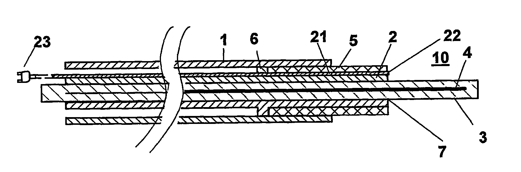
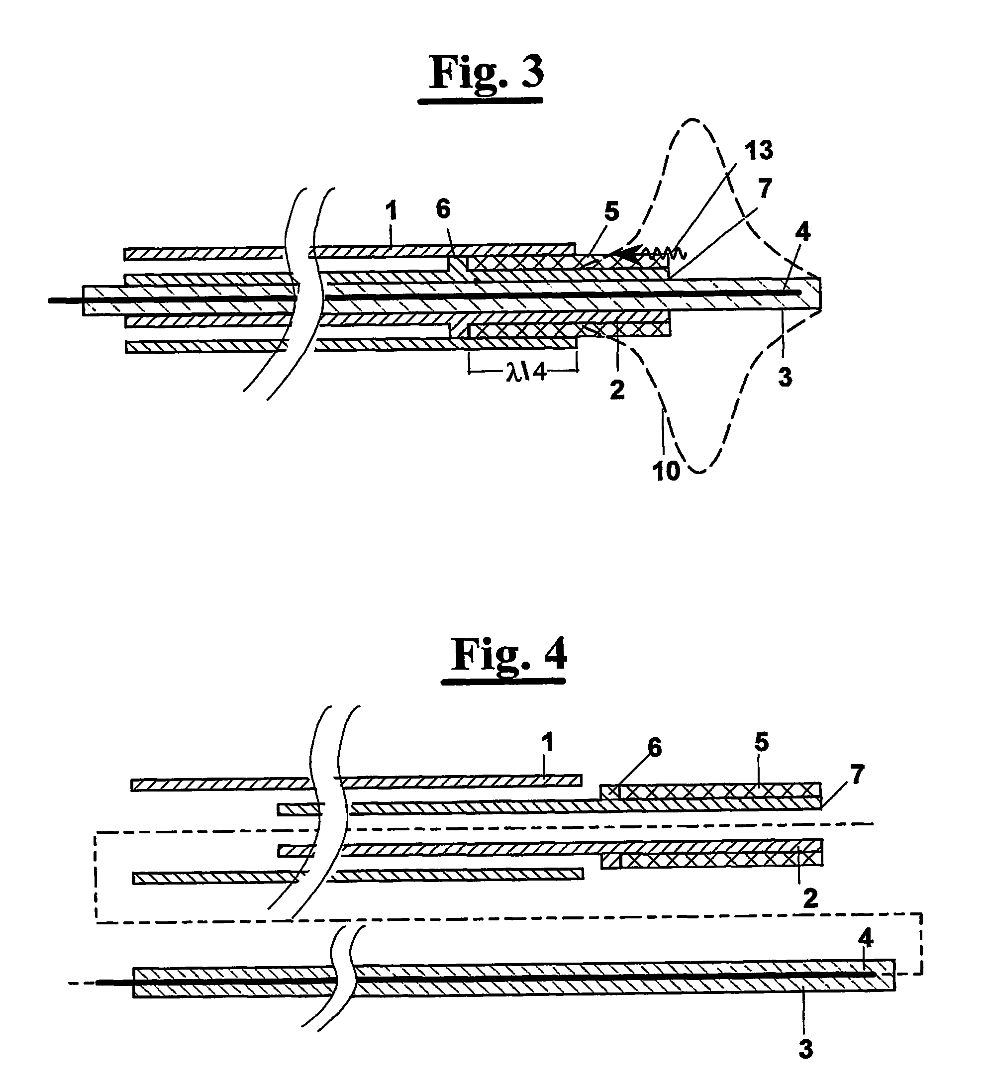
[0053] In FIG. 3 an axial cross section is shown of an antenna according to the invention inserted in a metal tube that consists in an biopsy needle 1, for example a 14 Gauge, outer diameter=mm 2.1 needle.

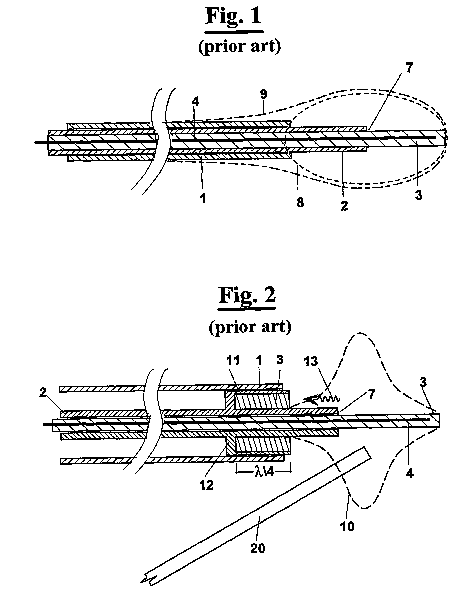
[0054] The antenna, in its active portion at the right of the figure, is a radiating dipole or monopole. More precisely, the antenna is formed by a co-axial tube having an external conductor 2, by a dielectric layer 3 and by a centersl conductor 4 immersed in the dielectric layer 3 that the insulates from the external conductor 2. The external conductor 2, as well known, end point indicated with 7, which is the feeding point the active portion of the antenna, said feed in gergo tecnico, where the emitted power, normally, is maximum.

[0055] According to the invention, is provided a plastics sheath insulating 5 and a collar metal 6. More precisely, this result can be obtained:

[0056] saldando on the external conductor of the antenna 2 the metal collar 6 in a predetermined position,

[005...


PUM


Abstract

The present invention relates to minimally invasive surgery techniques. It provides a method for manufacturing an antenna for percutaneous acute hyperthermia microwave applications of the monopole or dipole co-axial type provided with trap, commonly called choke, for blocking the propagation of the backwards reflecting wave towards the generator. The miniaturisation of the device allows a use minimally invasive for interstitial hyperthermia in medicine and surgery, in particular for oncology. The method of manufacturing the antenna provides a metal needle (1) for the introduction of the antenna (2, 3, 4) in the target tissue. On the external conductor (4) of the antenna (2) a metal collar (6) is connected in a predetermined position; a plastics sheath (5) is applied in order to cover the external conductor (2) in the portion between the feed (7) and the collar (6); the inner wall of the metal needle (1) wherein the antenna is inserted is then used for containing and guiding the collar (6) and the sheath (5); in particular, the collar (6) being in electrical contact with the inner wall of the metal needle (1). An antenna is thus obtained with choke of variable length and with miniaturized diameter. A thermocouple can be introduced through the choke that protrudes the directly in the "feed" zone.

Description

[0001] The present invention relates to minimally invasive surgery techniques, for interstitial, percutaneous, laparoscopic, endoscopic and intrasurgery applications in medicine and surgery, especially in oncology.[0002] More precisely, it relates to a microwave antenna, for hyperthermia, operating from 37C up to over 100C, of the monopole or dipole co-axial type equipped with "trap", commonly called choke, for blocking the propagation of the reflecting wave that turns back towards the generator.[0003] Furthermore the invention relates to a method of construction of such an antenna.DESCRIPTION OF THE PRIOR ART[0004] Hyperthermia in oncology is method used for over 30 years for treatment of cancer (Hahn GM, Hyperthermia and Cancer, Plenum Press, in the York, 1982). It consists in heating the cancer cells to obtain their necrosis directly or with additional use of other methods such as radiotherapy, chemotherapy or other surgery techniques.[0005] For heating tissues, in particular for...

Claims


Application Information

Patent Timeline
IPC IPC(8): A61B18/18A61N5/04H01Q1/44H01Q9/26H01Q9/30
CPCA61B18/18H01Q9/30A61B18/1815
Inventor LONGO, IGINIO
Owner CONSIGLIO NAT DELLE RICERCHE
Why Eureka
Try Eureka