Hydrogen enrichment scheme for autothermal reforming

a technology of hydrogen enrichment and autothermal reforming, which is applied in the direction of energy input, lighting and heating apparatus, separation processes, etc., can solve the problems of light pressure drop, achieve the effect of reducing the duty of the heater 104, facilitating the introduction of the burner, and reducing the molar ratio of steam

Inactive Publication Date: 2004-03-25
KELLOGG BROWN & ROOT INC
View PDF1 Cites 37 Cited by
  • Summary
  • Abstract
  • Description
  • Claims
  • Application Information

AI Technical Summary

Benefits of technology

0017] According to the principles of the present invention, a portion of the syngas effluent is recovered downstream from the reformer 110 and recycled via line 122 and thermo-compressor ejector 124 into line 106. Thermo-compressor ejectors are commercially available, and are capable of operating at the temperatures in lines 106 and 112. The thermo-compressor ejector 124 uses the fluid in line 106 to continuously educt recycle gas from line 122 in a consistent ratio into line 106A. At the same time, the ejector 124 thoroughly mixes the streams to facilitate introduction to the burner in the reformer 110 for continuous firing.
0018] The ratio of recycle in line 122 to heater effluent in line 106 should be sufficient to maintain an adequate hydrogen content in line 106A downstream from ejector 124 to avoid soot formation in the reformer 110, preferably from 5 to 50 mole percent hydrogen, more preferably from 20 to 40 mole percent hydrogen in line 106A, dry basis. The molar ratio of fluids in line 122 to line 106 is preferably from 0.2 to 1.0, more preferably from 0.3 to 0.6. The presence of the hydrogen in line 106A, as well increased steam and temperature from the recycle, thus allows the reformer 110 to operate continuously with a lower molar ratio of steam to carbon than in prior art autothermal reformers, i.e. below about 3.6, preferably from 0.6 to 3.0. The particular-ratio of steam to carbon is thus selected to optimize the composition of the reformer effluent for the downstream process needs, i.e. a different ratio may be employed for ammonia synthesis as opposed to methanol synthesis, hydrogen generation for a refinery or Fisher-Tro

Problems solved by technology

There is a slight pressure drop between the raw feed steam-natural gas mixture and the reformer feed due to a loss across the ejector, which requires the raw feed mixture to be supplied at a slightly hig

Method used


Image

  • Hydrogen enrichment scheme for autothermal reforming
  • Hydrogen enrichment scheme for autothermal reforming
  • Hydrogen enrichment scheme for autothermal reforming

Examples


Embodiment Construction

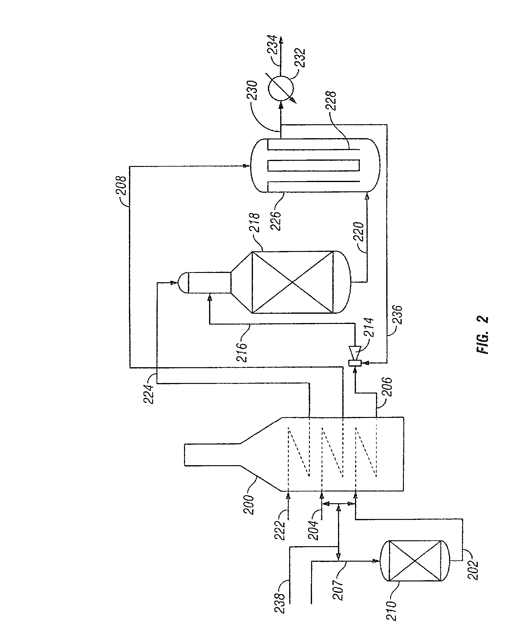
[0025] Some specific examples of operating conditions for the reforming according to the FIG. 2 embodiment are shown in Table 1 for various overall steam-carbon ratios and oxidants:

[0026] [t2]

1TABLE 1 Raw Feed Total Feed H2 in Steam- Recycle / Steam- Total Carbon Feed Ratio Carbon H2 ex-Pre- Feed Ratio (line Oxidant (line 236 / Ratio (line reformer (line 206) (line line 206) 216) (line 212) 216) (molar) 222) (molar) (molar) (mole %) (mole %) 2.7 Air 0.33 3.2 14.6 27.4 2.5 Air 0.33 2.9 13.9 26.7 2.5 Air 0.66 3.2 13.9 32.1 2.7 98% O2 0.33 3.3 14.6 34.8 2.0 98% O2 0.33 2.4 12.3 31.9 1.5 98% O2 0.33 1.7 10.5 29.2 1.5 98% O2 0.66 1.9 10.5 38.4 0.6 98% O2 0.66 0.64 6.6 30.2 0.6 98% O2 0.40 0.6 6.6 24.1 2.5 98% O2 0.33 2.9 13.9 28.6 2.5 98% O2 0.66 3.3 13.9 35.0

[0027] Having described the invention by way of the embodiments illustrated above, many variations and modifications of the invention will be apparent to those skilled in the pertinent art. It is intended that all such variations and ...


PUM

PropertyMeasurementUnit
Temperatureaaaaaaaaaa
Pressureaaaaaaaaaa
Sizeaaaaaaaaaa

Abstract

Recycling a portion of autothermal reformer effluent into the steam-hydrocarbon feed stream with a thermo-compressor ejector is disclosed, using the preheated feed mixture as motive fluid. Syngas recycle-motive fluid molar ratios are 0.2-1.0, selected to optimize the overall configuration. The recycle introduces hydrogen and steam into the feed, and elevates the feed temperature, for operating the reformer in a soot-free regime. There is some pressure drop between the raw feed steam-natural gas mixture and the reformer feed, which requires the raw feed mixture to be supplied at a higher pressure, but this is offset by the lower pressure drop in the process heater and other upstream and downstream equipment due to lower quantities of steam. The feed pre-heater can have a lower duty, and the upstream and downstream equipment can be reduced in size, while the size of the autothermal reformer is about the same compared to the size needed for operation without effluent recycle.

Description

BACKGROUND OF INVENTION[0001] This invention relates to autothermal reforming of steam and hydrocarbon to make syngas, used in manufacturing ammonia, methanol, Fisher-Tropsch synthesis, petroleum upgrading and other processes, and more particularly to autothermal reforming with recycle of a portion of the syngas to facilitate lower steam to carbon ratios without soot formation.[0002] Autothermal steam reforming is well known and has been commercialized successfully. A mixture of steam and hydrocarbon is supplied to the autothermal reformer with air, oxygen-enriched air or oxygen and goes through partial combustion using a specially adapted burner at the top entry. The partial combustion products react on a fixed catalyst to form a syngas that usually includes steam, hydrogen, carbon monoxide and carbon dioxide. This process represents a fundamentally simple, reliable and cost effective technology for syngas production.[0003] One operational characteristic desired for improvement, ho...

Claims


Application Information

Patent Timeline
IPC IPC(8): B01J8/06C01B3/38C10G11/22
CPCB01J8/067B01J2208/00212B01J2208/00274B01J2219/00006C01B3/382C01B2203/82C01B2203/0244C01B2203/0844C01B2203/142C01B2203/143C01B2203/148C01B2203/0233Y02P20/129
Inventor SINGH, SHASHI PRAKASHMALHOTRA, AVINASH
Owner KELLOGG BROWN & ROOT INC
Why Eureka
Try Eureka