Particle filter having a catalytically active coating to accelerate burning off accumulated soot particles during a regeneration phase

a technology of catalytic activity and filter, which is applied in the direction of filtration separation, exhaust treatment, electrical control, etc., can solve the problems of increasing fuel consumption, reducing the ignition temperature of soot particles, and the filter itself is not easily regenerated, so as to reduce the co and hc emissions.

Inactive Publication Date: 2004-04-08
UMICORE AG & CO KG
View PDF34 Cites 27 Cited by
  • Summary
  • Abstract
  • Description
  • Claims
  • Application Information

AI Technical Summary

Benefits of technology

[0054] Another advantage of the invention, compared with the processes known in the state of the art, is the fact that no ash from the additives can collect in the filter. There are only oil ash deposits, as also happened with the other processes. The maintenance interval for removal of such ash from the filter by appropriate flushing or washing processes with water can then be extended substantially compared to the processes with fuel additives. As appropriate experiments have shown, the catalytic coating of the filter is resistant to such washing processes.
[0055] Various types of filters are suitable for the process, such as wall flow filters, filters of ceramic fibers or ceramic or metallic foam, and filters of wire mesh. It is preferable to use wall flow filters of silicon carbide, cordierite, or sodium zirconium phosphate. These filters are only coated from the inlet side. The concentration of the coating is preferably between 20 and 200 grams per liter of filter body, while the concentration of the platinum group metal(s) is preferably 0.5 to 10 grams / liter of filter body.
[0056] The present invention may be used to clean exhaust gases of vehicles with diesel engines. For carrying out the process according to this invention the power system of such a motor vehicle contains a diesel engine and an exhaust gas cleaning system with a diesel oxidation catalyst and a particle filter. The exhaust gas temperature of the engine can be increased for filter regeneration by post-injecting fuel into the diesel engine cylinders during the expansion phase. The particle filter of this power system is provided with the catalytic coating described above, which provides both a NO.sub.x storage coating and a noble metal component for oxidation of carbon monoxide and, if necessary, of hydrocarbons. One particularly advantageous embodiment of this drive system contains an oxidation catalyst in a position near the engine, ahead of the particle filter, which is dimensioned,so that when fuel is post-injected, only a small part of the fuel reacts. This oxidation catalyst is preferably introduced ahead of or immediately behind the turbocharger in the exhaust gas line of the diesel engine. Because of its position near the engine, it reaches its operating temperature very rapidly, so that it can reduce part of the CO and HC emissions during a cold start. But because of its small volume, it cannot convert all the hydrocarbons introduced by post-injection during a regeneration of the particle filter, so that most of the post-injected fuel gets to the particle filter, where it is burned on contact with the oxidative function of the catalytic coating.
[0057] To produce the catalytic coating for the filter, the solid components of the coating are processed into a preferably aqueous coating suspension. Then the filter is coated with this suspension on what will later be the inlet side for the exhaust gas, using known processes. Optionally, the upstream and downstream sections of the filter are also coated. Then the suspension is dried and calcined. The platinum group metal(s) can be deposited on the solid components of the coating just before preparation of the coating suspension, or they can be added to the aqueous coating suspension in the form of soluble precursor compounds. Alternatively, the platinum group metal(s) can be introduced into the coating only after the coating has been prepared, by a supplemental impregnation with a solution of the precursor compounds. After the impregnation has been finished, the filter body must again be dried and calcined.EXAMPLES
[0058] The present invention is illustrated by the following examples. These are merely illustrative and should not be construed as limiting the scope of the invention.

Problems solved by technology

Unfortunately, while they are effective at filtering, the filters themselves are not easily regenerated.
But modern diesel engines, generally reach such temperatures only at full load.
Such measures are linked to increased fuel consumption.
There the function of the oxidation catalyst is to oxidize the hydrocarbons and the carbon monoxide released during the filter regeneration, thus making them harmless.
Reduction of the soot ignition temperature by a soot ignition coating or by a fuel additive generally cannot assure regeneration of a filter at low engine load.
Unfortunately, it is not usual for that proportion to be sufficient.
However, it has not yet been possible to assure the post-injection required to initiate the filter regeneration at every operating point.
The known processes and exhaust gas systems that add an additive to the fuel to reduce the soot ignition temperature have the disadvantage that after regeneration of the filter, the additive accumulates in the filter as an ash, such as cerium ash.
That ash substantially increases the exhaust gas backpressure, resulting in continuously increasing fuel consumption.
A further disadvantage of this system, and those systems that operate with uncoated filters, is the high carbon monoxide emissions that occur during the spontaneous or active filter regeneration.
The soot collected in the filter, at a loading of up to 8 grams of soot per liter of filter volume burns within a few minutes, which results in incomplete oxidation of the soot particles and in substantial CO emissions.

Method used


Image

  • Particle filter having a catalytically active coating to accelerate burning off accumulated soot particles during a regeneration phase
  • Particle filter having a catalytically active coating to accelerate burning off accumulated soot particles during a regeneration phase
  • Particle filter having a catalytically active coating to accelerate burning off accumulated soot particles during a regeneration phase

Examples


example 1

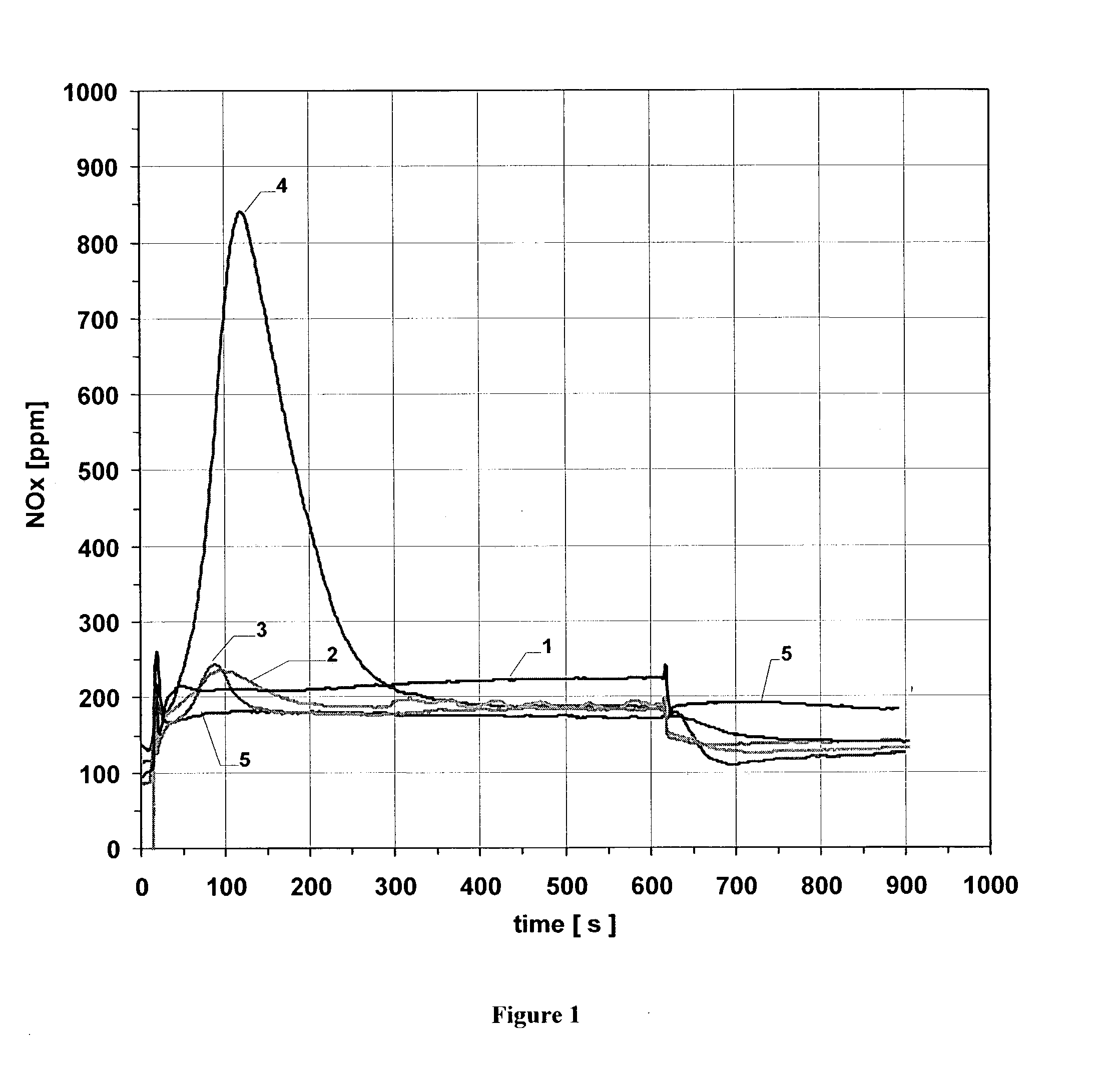
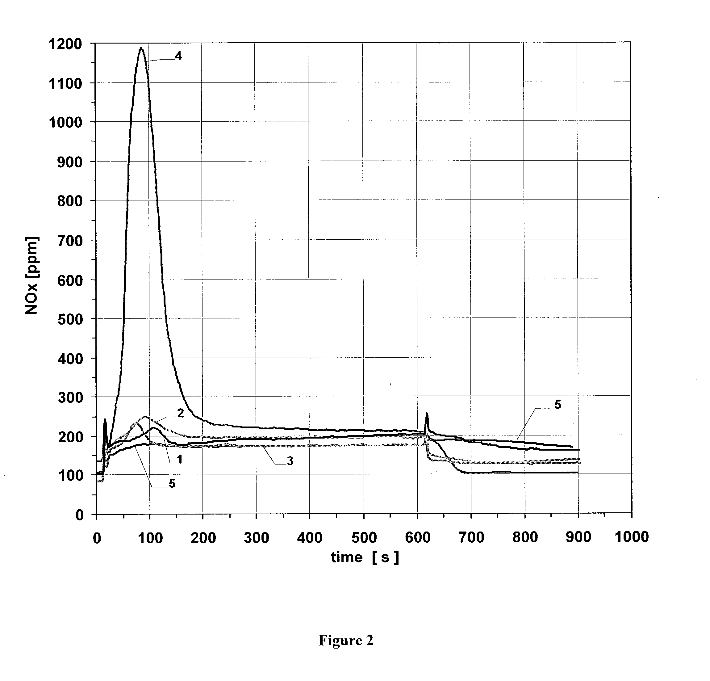
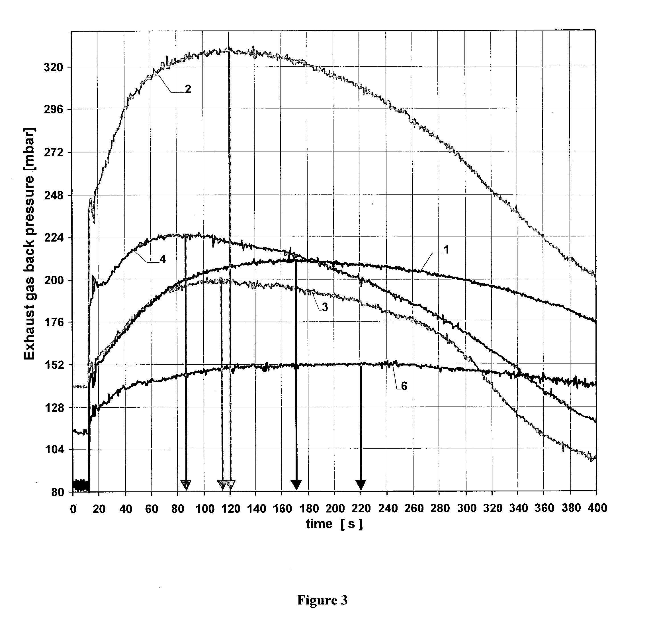
[0059] The reduction of the soot ignition temperature and the acceleration of the soot combustion by various NO.sub.x storage coatings were investigated in the following examples and comparison examples. The investigations used cylindrical wall flow filters of silicon carbide with a cell density (number of flow channels per cross-sectional area of the filter) of 41 cm.sup.-2, a length of 15.2 cm and a diameter of 14.4 cm (volume ca. 2.5 liters).

[0060] Particle filters were coated with the coating compositions listed in Table 1:

1TABLE 1 Coating compositions Coating components Weight ratio Comparison Pt / CeO.sub.2MnO.sub.2 CeO.sub.2:MnO.sub.2 = 1:1 example 1 Comparison Pt / CeO.sub.2MnO.sub.2 + MgO CeO.sub.2:MnO.sub.2:MgO = example 2 2:2:1 Comparison Pt / CeO.sub.2MnO.sub.2 + BaCO.sub.3 CeO.sub.2:MnO.sub.2:BaCO.sub.3 = example 3 2:2:1 Example Pt / CeO.sub.2MnO.sub.2 + BaCO.sub.3 + CeO.sub.2:MnO.sub.2:BaCO.sub.3:MgO = MgO 2:2:1:1

[0061] Each of the cerium oxides used was stabilized with 30% by...


PUM

PropertyMeasurementUnit
temperaturesaaaaaaaaaa
atomic numbersaaaaaaaaaa
temperatureaaaaaaaaaa

Abstract

The present invention is directed to a particle filter to remove soot from the exhaust gas of a diesel engine. The particle filter contains a catalytically active coating on a filter body to accelerate bum-off during a regeneration phase of the soot particles collected on the filter. The particle filter comprises a catalytic coating containing compounds of barium, compounds of magnesium, and at least one element of the platinum group metals. The invention is further directed to a process for accelerated combustion of soot particles collected on the filter from lean exhaust gas of a diesel engine in which the soot particles have a soot ignition temperature and the particle filter is actively regenerated from time to time by raising the temperature of the particle filter above the soot ignition temperature and burning off the soot particles.

Description

[0001] The present invention is directed to a particle filter for removal of soot from diesel engine exhaust gas.BACKGROUND OF INVENTION[0002] Particle filters remove soot particles from the lean exhaust gas of combustion engines, thereby preventing their emission into the atmosphere. Various filter concepts may be employed to accomplish these goals, including but not limited to wall flow filters, filters of ceramic fibers or of ceramic or metallic foams, and filters of wire meshes. These technologies have proven extremely successful at accomplishing their designed tasks. In fact, they can attain filtration levels greater than 95%. Unfortunately, while they are effective at filtering, the filters themselves are not easily regenerated.[0003] Carbon soot, which is one of the major substances trapped on particle filters, burns spontaneously only at temperatures of about 600.degree. C. or greater. But modern diesel engines, generally reach such temperatures only at full load. Therefore,...

Claims


Application Information

Patent Timeline
Patent Type & Authority Applications(United States)
IPC IPC(8): B01D39/14F01N3/02B01D46/42B01D53/94B01D53/96B01J23/58B01J27/232F01N3/023F01N3/035F01N3/24F02D41/02F02D41/04F02D41/40
CPCB01D53/944B01D53/96B01J23/58F01N3/0231Y10S502/524F01N2430/085F02D41/029F02D41/405Y02T10/44F01N3/035Y02T10/40B01D39/06
Inventor PFEIFER, MARCUSVAN STETTEN, BARRYKUHN, CHRISTIANSTAAB, ROGERRUWISCH, LUTZ MARCKATTWINKEL, PETERGIESHOFF, JURGENLOX, EGBERTKREUZER, THOMAS
Owner UMICORE AG & CO KG
Why Eureka
Try Eureka