
Metallic vapor deposition lens provided with a protection coat and a method of producing the same

Inactive Publication Date: 2004-04-15
NICOH OPTICAL
View PDF5 Cites 2 Cited by
  • Summary
  • Abstract
  • Description
  • Claims
  • Application Information

AI Technical Summary

Benefits of technology

[0008] The invention is further to provide a method of efficiently and economically producing a metallic vapor deposition lens provided with a protection coat that is smooth on the surface and excels in abrasion-proof characteristic, which protection coat is made of a casting resin essentially consisting of diethylene glycol bis(allyl carbonate) characteristic in lower viscosity and higher ductility.
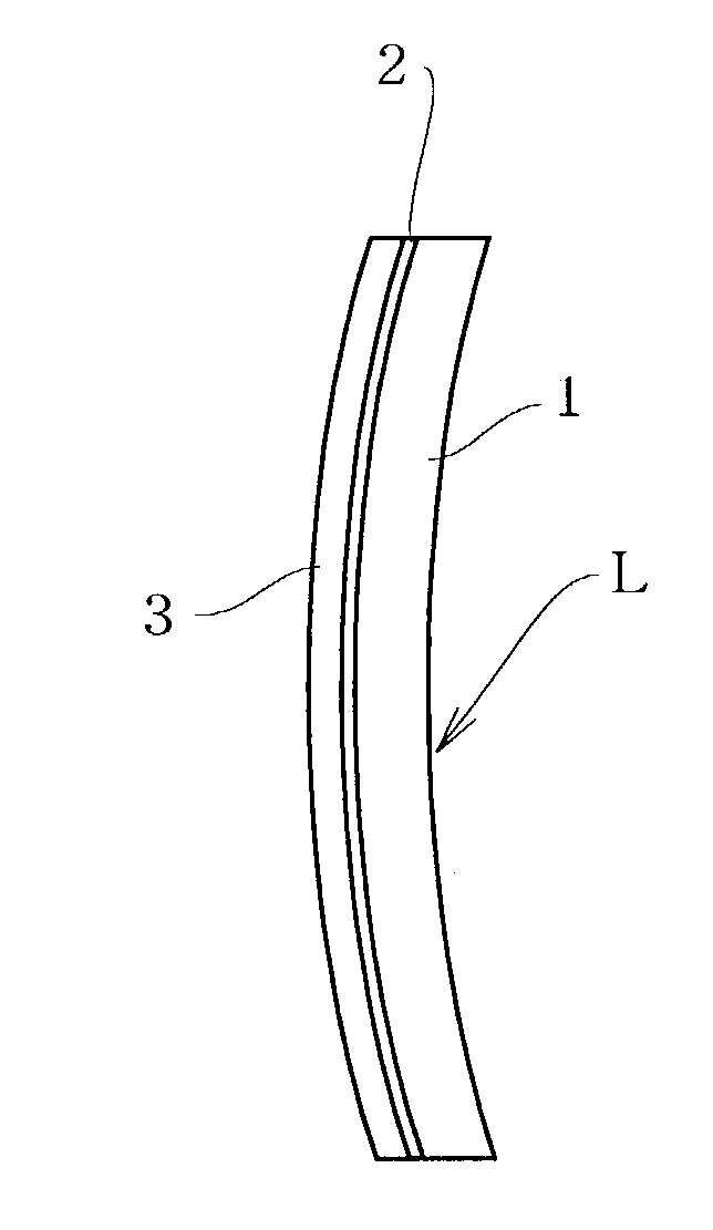
[0009] Namely, in order to solve the above issues, the metallic vapor deposition lens provided with a protection coat according to the invention is characterized in that a vapor deposition filmy layer 2 made from a metallic material m is formed on at least one side surface of a lens proper 1 and a polymerization hardening layer 3 made from diethylene glycol bis (allyl carbonate) is overlaid on the filmy layer 2 so as to protect the surface of the vapor deposition filmy layer 2.
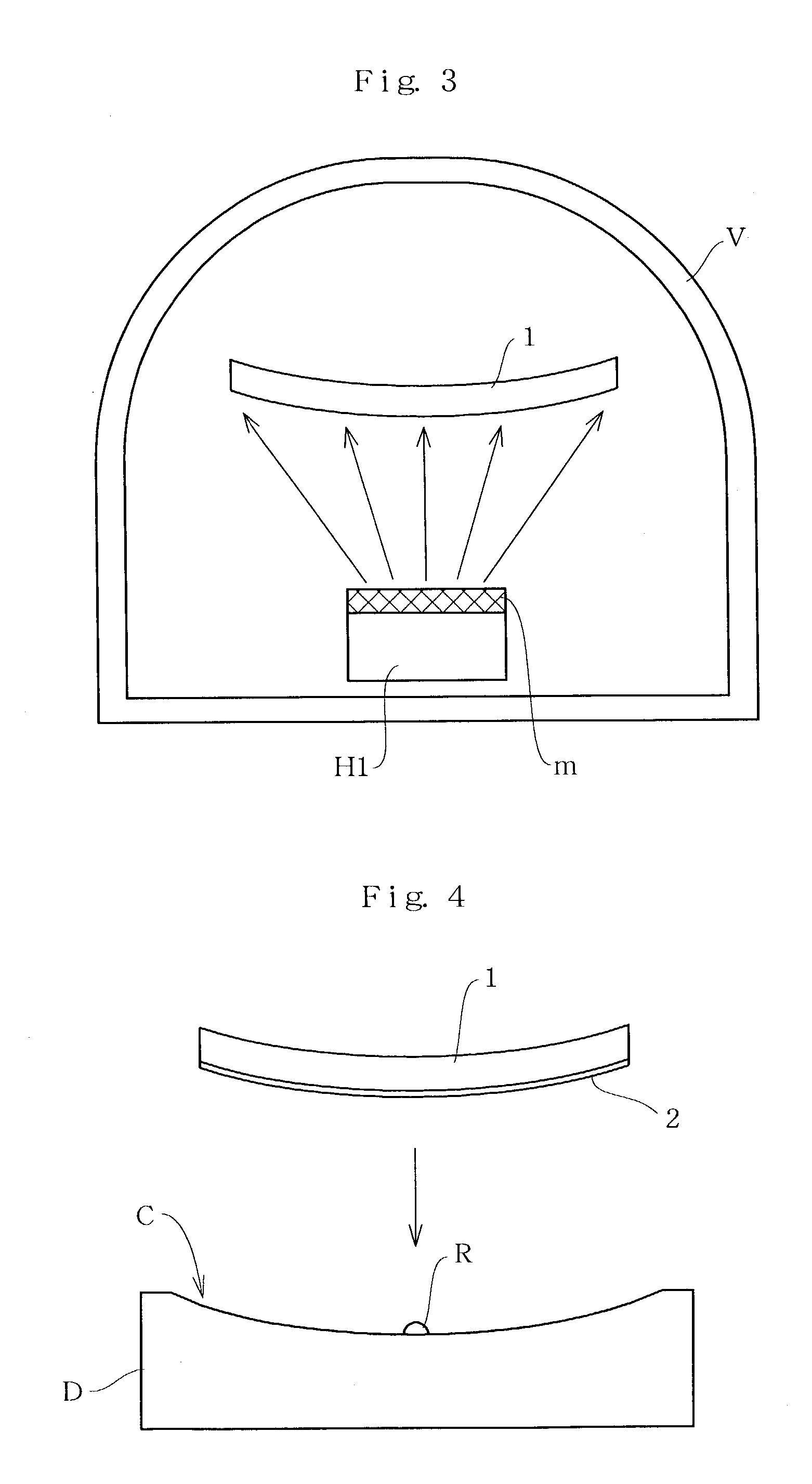
[0014] Then, the method of producing a metallic vapor deposition lens provided with a protection coat according to the invention is characterized in comprising the steps of placing a lens proper 1 in a vacuum chamber V and depressurizing the chamber; vaporizing a metallic material m in the chamber as depressurized by means of a heating means and filming the metallic material as vaporized on a convex surface of the lens proper 1 so as to form a metallic deposition filmy layer 2; dropping a casting resin R of lower viscosity essentially consisting of diethylene glycol bis(allyl carbonate) into a casting die D provided with a concave cavity C corresponding to a concave surface of the lens proper 1; placing the metallic deposition filmy layer 2 formed on the convex surface of the lens proper 1 as taken out of the vacuum chamber V on a concave surface of the cavity C so as to uniformly spread and attach the casting resin R on the metallic deposition filmy layer 2 and polymerizing and hardening the casting resin R as spread under heating treatment; and taking out an integral lens prototype Lb from the casting die D and subjecting the lens prototype to finishing treatment so as to produce the metallic vapor deposition lens provided with a protection coat L.

Problems solved by technology

However, such metallic vapor deposition lens as mentioned above is poor at abrasion-proof characteristic so that the metallic deposition layer is easily peeled off by an inadvertent contact therewith.
Under such circumstances as mentioned above, in order to protect the metallic deposition layer, conventionally, the method of dipping the lens into the fused resin material is known, which method causes the non-uniform attachment of the resin coat on the lens surface owing to the viscosity-related unbalanced spreading of the fused resin material thereon.
This unavoidably causes the inconsistency of the attached resin coat on the finished lens surface, which results in the appearance of the wavy patterns with rainbow colors on the surface owing to the difference in thickness of the attached resin coat and the interference of the visible light.

Method used


Image

  • Metallic vapor deposition lens provided with a protection coat and a method of producing the same
  • Metallic vapor deposition lens provided with a protection coat and a method of producing the same
  • Metallic vapor deposition lens provided with a protection coat and a method of producing the same

Examples


modified example

[0029] Then, the modified example of the metallic vapor deposition lens according to the invention is described with reference to FIG. 2. The difference between the above embodiment and the modified example lies in that a hardening coat 4 having 0.05 mm in thickness, which coat is manufactured by Kabushiki Kaisha Tokuyama under the trade name of `TS-56T`, is laminated on the convex side surface of the polymerized hardening layer 3 and the concave side surface of the lens proper 1 respectively.

[0030] Further, the polymerized hardening layer 3 formed on the convex side surface of the lens proper 1 is thickened while the lens proper 1 is thinned accordingly.

[0031] In this modification, the finished lens L has 70 mm in diameter wherein the lens proper 1 has 3 mm in thickness and the metallic deposition filmy layer 2 has 1 .mu.m in thickness, and the polymerized and hardening layer 3 formed on the convex side surface of the lens proper 1 has 3 mm in thickness and the hardening coat 4 has...

production example

[0033] The method of producing the metallic vapor deposition lens according to the invention is described below with reference to FIGS. 2 through 6.

[0034] To begin with, the convex side surface of the lens proper 1 is subjected to vapor deposition so as to form a metallic deposition filmy layer 2 thereon. Concretely speaking, the lens proper 1 is placed in a chamber V of a vacuum deposition means and such metallic material m as chromium (Cr), chromium oxide (Cr.sub.2O.sub.3), silicone dioxide (SiO.sub.2), zirconium dioxide (ZrO.sub.2), titanium dioxide (TiO.sub.2), alumina (Al.sub.2O.sub.3) and gold (Au) is heated under the temperature ranging from 1100 to 1800 (K) by means of a heating means Hi (an electron gun being exemplified in this embodiment) and vaporized with the atmosphere within the chamber depressurized to of the order of 10.sup.-5 (Torr), which vaporized material is attached on the convex side surface of the lens proper 1.

[0035] The above metallic deposition filmy layer...


PUM

PropertyMeasurementUnit
Thicknessaaaaaaaaaa
Metallic bondaaaaaaaaaa
Ductilityaaaaaaaaaa

Abstract

A metallic vapor deposition lens provided with a protection coat is provided, the surface of which lens is finished smooth and good at abrasion-proof characteristic. The metallic vapor deposition lens of the invention is characterized in that a filmy layer 2 made from a metallic material m is formed on at least one side surface of a lens proper 1 by vapor deposition and a polymerized and hardening layer 3 made from diethylene glycol bis(allyl carbonate) is overlaid on said metallic deposition filmy layer 2 so as to protect the surface of said filmy layer 2. The coat formation made from this diethylene glycol bis(allyl carbonate) resin over the surface of said metallic deposition filmy layer prevents the same surface from being scratched off and the higher ductility and the lower viscosity of said resin allows the protection coat to be uniformly formed without inconsistency so as to prevent the wavy patterns with rainbow colors owing to the difference in thickness and the interference of the visible light from appearing on the lens surface. This avoids giving a strange look on the wearer's face.

Description

[0001] The present application claims the priority of Japanese Patent Application No.2002-298347 filed on Oct. 11, 2002, which application is incorporated herein by reference.TECHNICAL FIELD[0002] The invention relates to the improvement of a metallic vapor deposition lens adopted for the spectacle lens and the sunglasses and the production method of the same, in more details, pertaining to such metallic vapor deposition lens provided with a protection coat as being smooth on the surface and excelling in abrasion-proof characteristic and the production method of the same lens.PRIOR ART[0003] As known, a polarized lens is generally adopted for the sunglasses, which polarized lens is arranged by attaching a polarized film on the glasses and one example of which is disclosed in Japanese Patent Application Laid-open No.2001-350122 (refer to Pages 3 through 5 and FIGS. 1 through 3).[0004] The recent progress of the lens processing technique leads to the development of a high-performance ...

Claims


Application Information

Patent Timeline
IPC IPC(8): B29C39/10B29L11/00G02C7/02C23C14/20G02B1/10G02C7/10
CPCG02B1/105Y10T428/31507G02B1/14
Inventor HAYASHI, HOKAO
Owner NICOH OPTICAL
Learn More