Gas sensor calibration system

a calibration system and gas sensor technology, applied in the direction of liquid/fluent solid measurement, instruments, electrochemical variables of materials, etc., can solve the problems of hazardous gas required for calibration, frequent non-compliance, waste of calibration gas, etc., to reduce the volume of gas space, reduce the consumption of expensive calibration gas, and reduce the length of the gas path

Inactive Publication Date: 2004-04-22
HONEYWELL ANALYTICS LTD
View PDF5 Cites 32 Cited by
  • Summary
  • Abstract
  • Description
  • Claims
  • Application Information

AI Technical Summary

Benefits of technology

0032] By reducing the volume of gas space between the source of pressurised calibration gas and the detector and by forming a gas tight seal between the calibration apparatus and a detector, the predetermined flow rate of calibration gas can be as low as 0.1 litre/minute .+-.20% and permits the sensor(s) to come to an equilibrium value quickly which reduces the consumption of expensive calibration gas. Also, because the detector can stop the flow of calibration gas immediately it detects the sensor output(s) have reached a

Problems solved by technology

Safety regulations require that the sensors within the detector are tested on each occasion that they are taken into a potentially hazardous environment and calibrated according to manufacturer's recommendations and that is indeed good commercial practice but it is frequently not complied with for reasons of cost and time.
Excess calibration gas flows out of the hood and is vented to atmosphere and so the procedure is wasteful of calibration gas, which is expensive.
In addition, the gas required for calibration could be hazardous and if substantial quantities are vented, calibration should be carried out in a controlled environment.
Typically a high flow rate of about 0.5 litres/minute are used since a lower rate is prone t

Method used


Image

  • Gas sensor calibration system
  • Gas sensor calibration system
  • Gas sensor calibration system

Examples


Embodiment Construction

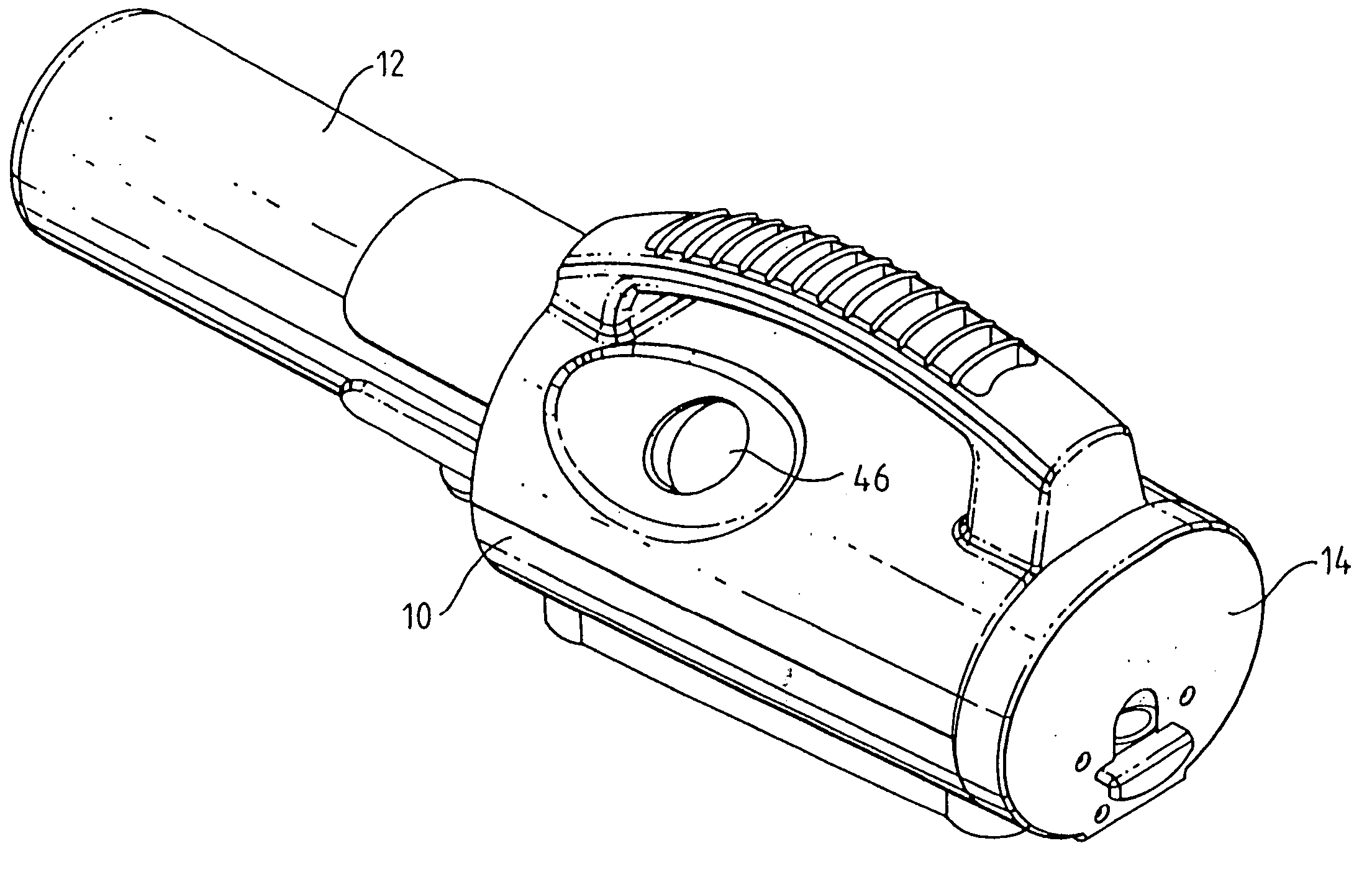
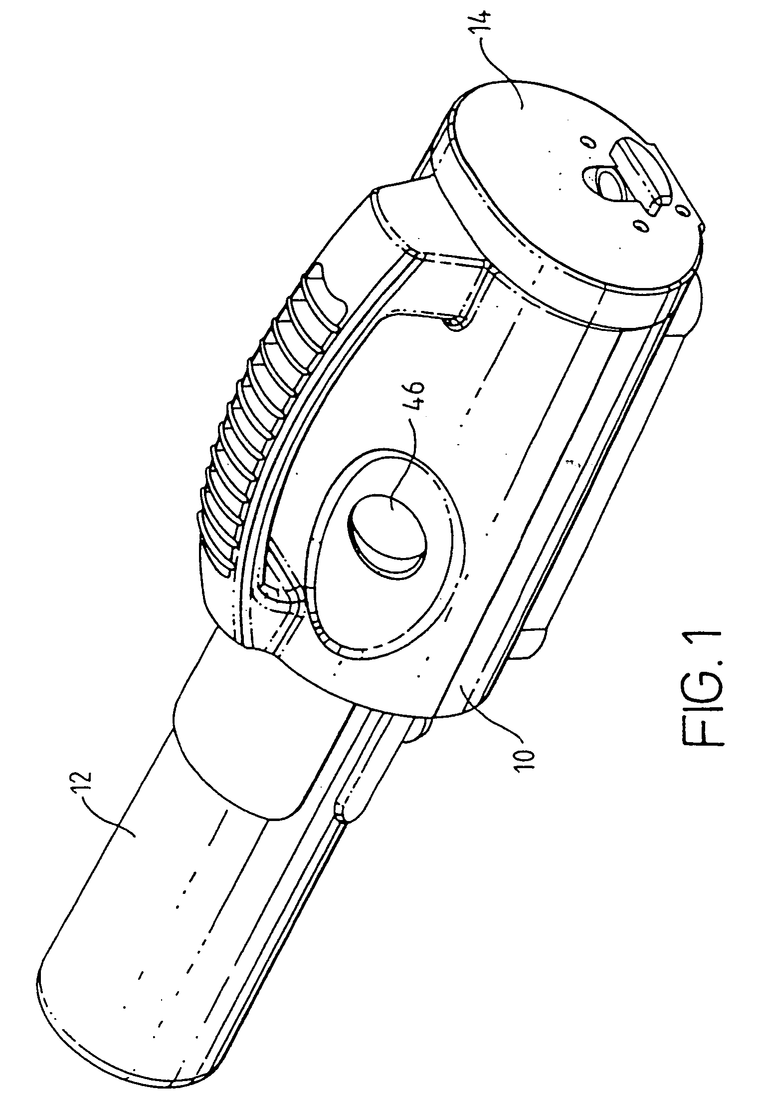
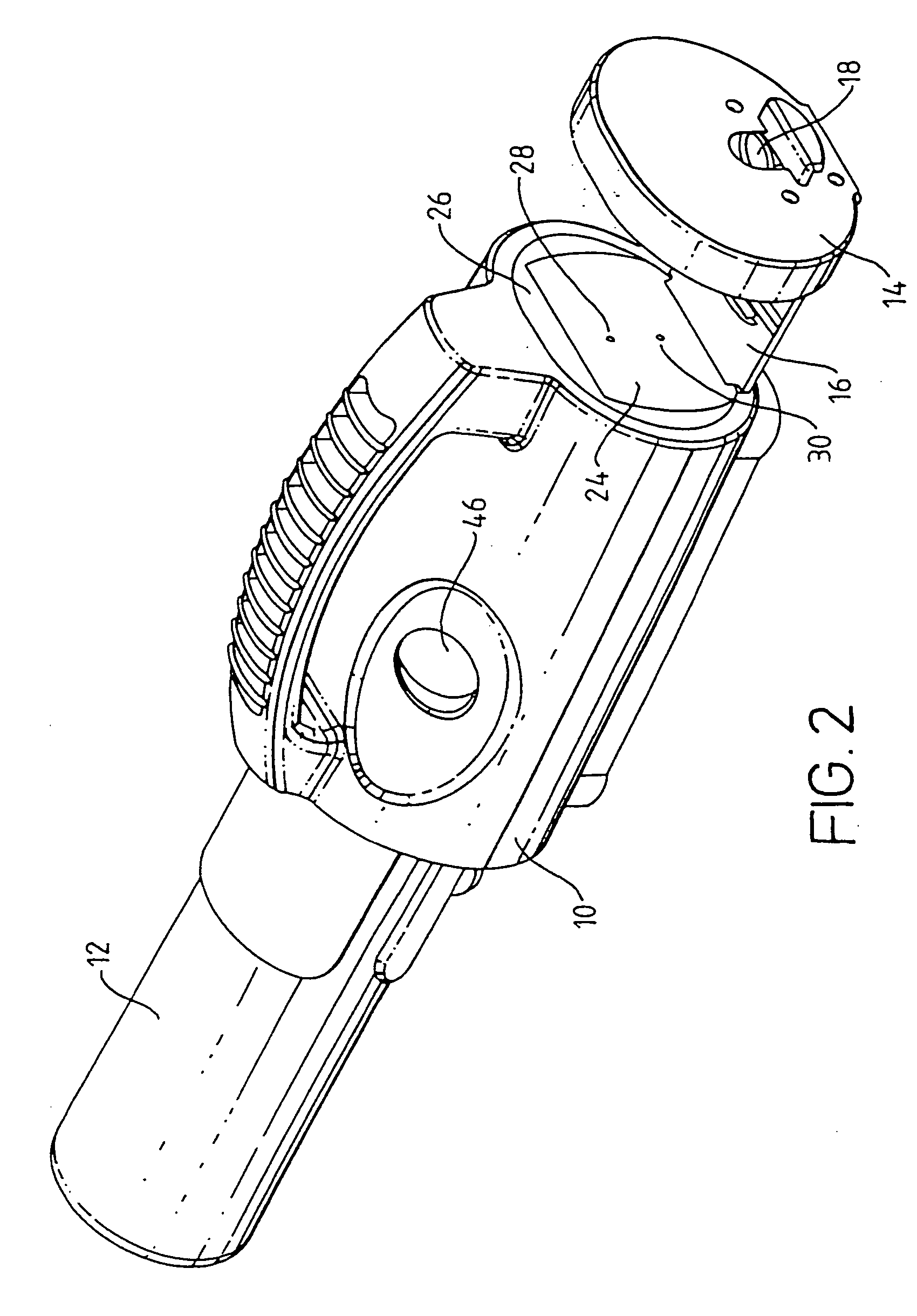
[0041] Referring initially to FIGS. 1 to 3, the apparatus comprises a housing 10 containing a cylinder 12 of pressurised calibration gas that holds a mixture of that a detector is or may be sensitive to, for example oxygen, carbon monoxide, flammable gases and hydrogen sulphide, in an inert carrier, e.g. nitrogen. The gases are present in known predetermined concentrations. The housing includes an end panel 14 that can be slid out (see FIG. 2) while still being attached to the main housing 10 by means of an arm 16. As will be more fully described below, the arm 16 is spring loaded by spring 20 to urge the end panel 14 towards the main housing. However, it can be latched in place by means of a latching mechanism that can be released by operating a latch 18. Thus, when the end panel 14 is pulled out, it is held in the open position shown in FIG. 2. However, when the latch 18 is operated, the latching mechanism is released and the end panel is pulled by a spring 20 (see FIG. 4) towards...


PUM


Abstract

An apparatus is described for calibrating at least one sensor within a gas detector (22), which detector has a gas inlet in fluid communication with the or each sensor, the apparatus comprising a housing (10) that contains: a) a surface (24) for abutting against the detector (22); b) a holder (14) for holding the gas detector (22) with respect to the housing (10) in such a manner that a region of the detector containing the gas inlet abuts against the surface (24) of the housing to form a sealed gas interface between the surface (24) and the detector (22); c) a connector for connecting a source of pressurised calibration gas (12) to the apparatus, d) a conduit (32) for delivering a calibration gas from the connector (34) to the interface between the detector and the apparatus housing, e) electrical connections (40) within the holder for forming electrical connections between the apparatus and a detector held within the holder, and e) a flow controller (34, 36) within the conduit for providing calibration gas at a predetermined level to the interface, the flow controller including an electrically-operated valve (36) being controllable for initiating and terminating the flow of calibration gas through the conduit (32) by means of signals received from the detector via the electrical connections (40). The whole calibration is controlled by he detector and not the calibration apparatus.

Description

[0001] The present invention relates to a system for calibrating gas sensors, which are used in gas detection instruments and gas analysers (the term "detector" will be used in this specification to cover both types of apparatus) to detect or analyse potentially hazardous environments to ensure that the sensors provide accurate readings.[0002] Portable gas detectors containing electrochemical gas sensors are well-known for monitoring potentially hazardous environments, for example mines, tunnels, sewers and other closed environments. Such detectors are generally of the type in which gas from the atmosphere comes into contact with the sensors(s) within the detector by diffusion. Electronic circuits within the detector convert the output signal from each sensor into a reading of the amount of gas detected. The sensor output per unit amount of gas can vary with time and hence periodic calibration is required to ensure that the detector reading is accurate. Safety regulations require th...

Claims


Application Information

Patent Timeline
IPC IPC(8): G01N27/00G01N1/00G01N27/26G01N33/00
CPCG01N33/0006G01N7/00
Inventor FORREST, STEVEN GERARD
Owner HONEYWELL ANALYTICS LTD
Why Eureka
Try Eureka