
Integrated thin film capacitor/inductor/interconnect system and method

a thin film capacitor and integrated technology, applied in the direction of instruments, semiconductor/solid-state device details, transportation and packaging, etc., can solve the problems of low breakdown voltage, inherently difficult manufacturing of both techniques, and difficult manufacturing of capacitor types, etc., to reduce the effective capacitance of the capacitor, reduce the effective series resistance, and increase the performance and reliability of the manufactured system

Inactive Publication Date: 2004-04-29
ULTRASOURCE
View PDF32 Cites 42 Cited by
  • Summary
  • Abstract
  • Description
  • Claims
  • Application Information

AI Technical Summary

Benefits of technology

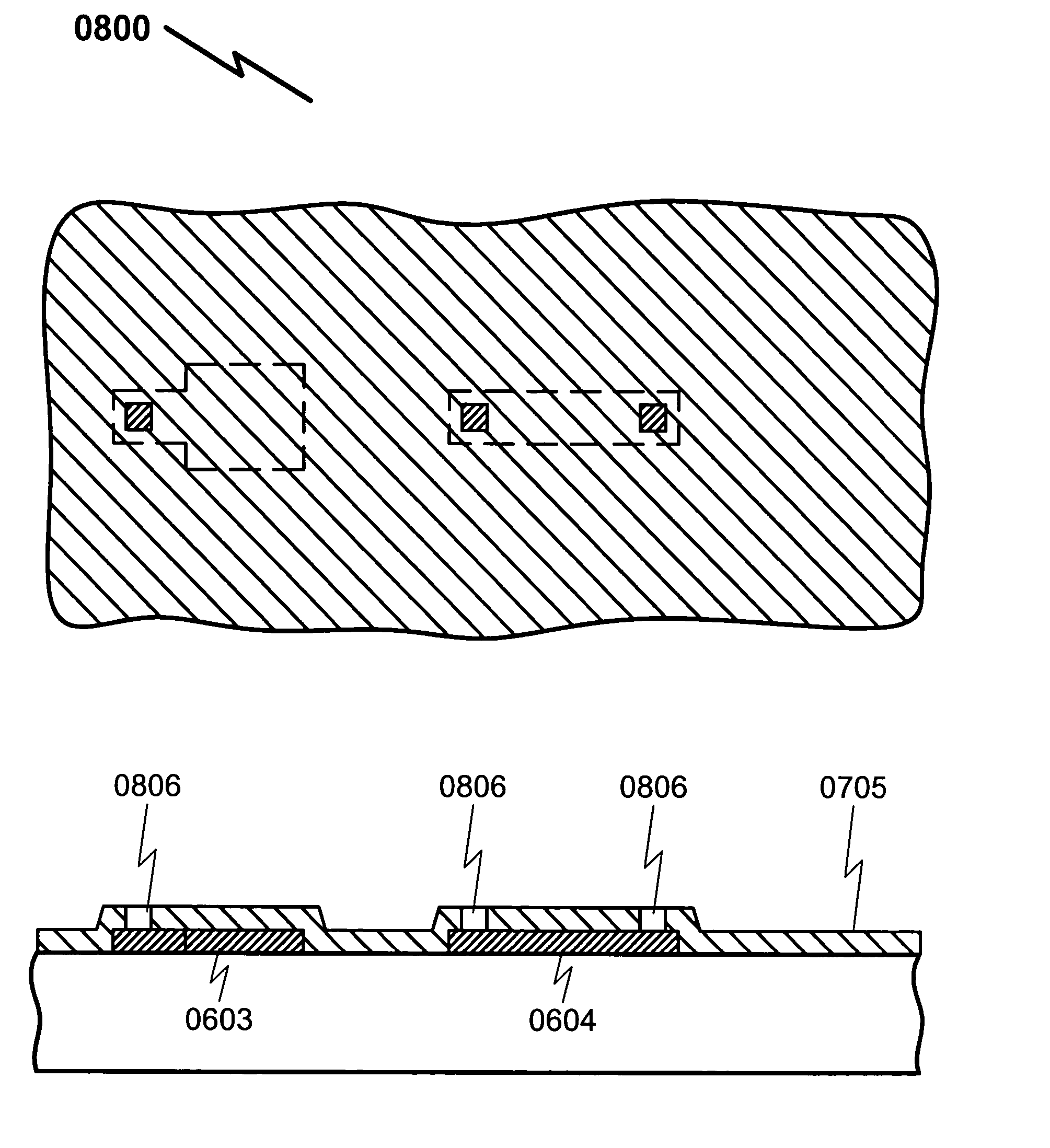
[0102] Key to this process is the thin application of metalization in step (1) to allow the use of a thin dielectric layer in step (2) to minimize the impact of step coverage reliability problems that are present in the prior art.System / Method Variations
[0138] FIG. 16 (1600) illustrates typical modeled performance of inductors using the teachings of the present invention. Key to interpretation of this graph is the fact that the inductor structure operates below the self-resonant point (1601) with inductive behavior (1602), but above this point it appears to have capacitive characteristics (1603). This is typical of all hybrid inductor structures, but the advantage in the present invention is that the self-resonant point (1601) and quality factor (Q) are higher than comparable prior art solutions, since the present invention inductors have lower series resistance values and tighter inductive coupling with lower parasitic capacitance.

Problems solved by technology

Both techniques are inherently difficult to manufacture as they need to address the issue of "step coverage" of the dielectric layer over the thick bottom electrode.
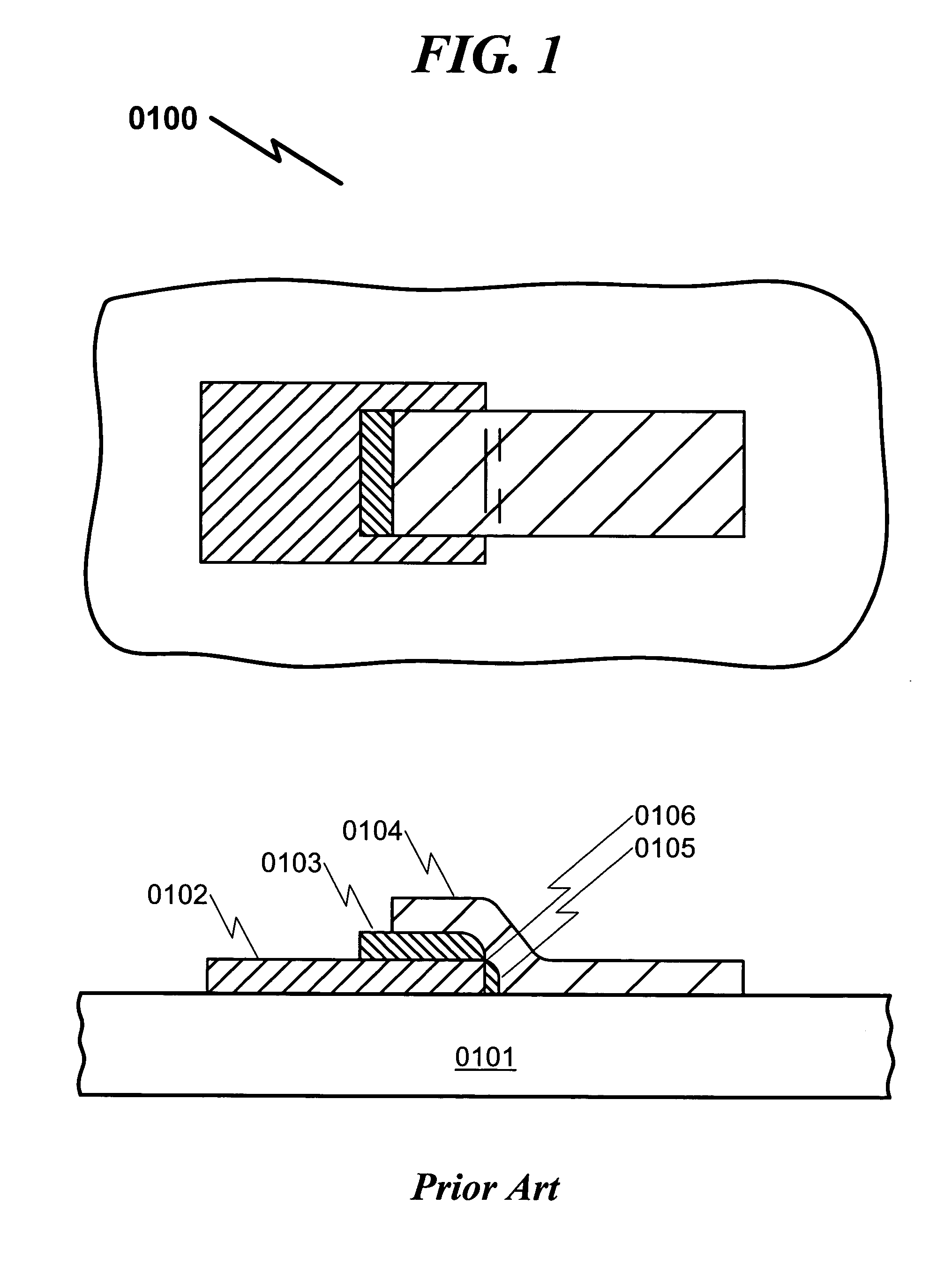
This type of capacitor is very difficult to manufacture as it presents many problems such as capacitance value reproducibility problems, shorting (0106) of the top electrode (0104) to the bottom electrode (0102) through the thin dielectric (0105), low breakdown voltage, low Q (quality factor) at high frequencies, and wire bonding challenges.
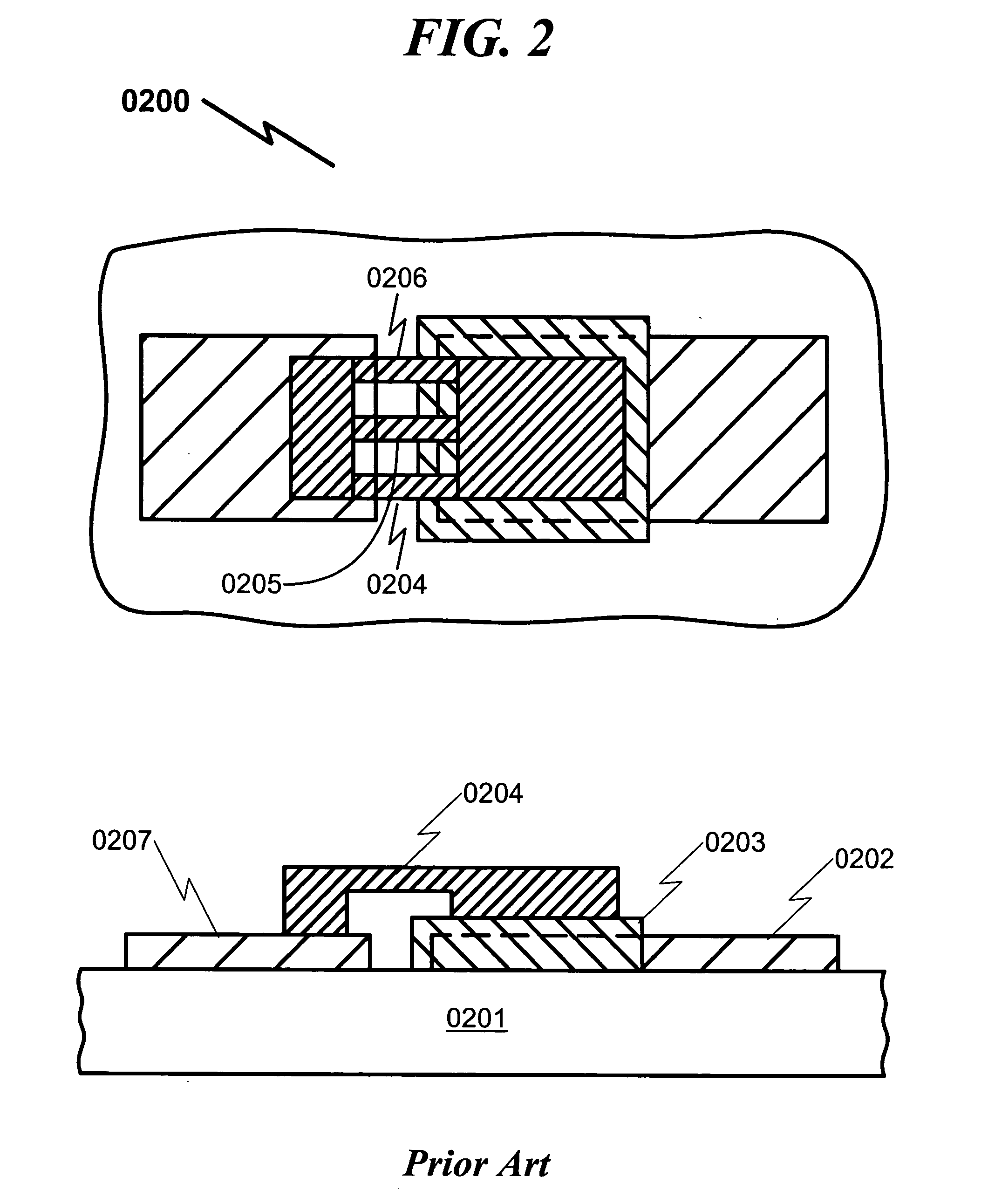
This process is inherently difficult because the lower electrode (0202) is relatively thick, thereby making it problematic to make contact to the upper electrode (0207) without shorting to the thick lower electrode (0202).
This method exhibits manufacturing and repeatability problems due to its very complex nature.
It is extremely expensive and problematic to produce.
It also suffers from reliability problems because the air bridges are vulnerable to shorts from handling.
The processes are typically expensive and therefore can usually only be used in high volume production or in specialty applications that are not cost sensitive.
Additionally, the air-bridge spans (0304) are fragile and can be deformed or collapsed by simple handling.
It is also important to note that due to the complex nature of the air-bridge process, it is extremely rare for air-bridge interconnects and air-bridge capacitors to be produced on the same device.
The addition of the insulating support (0403) under the span (0402) increases the complexity and cost of the supported crossover process.
It is again important to note that due to the complex nature of the supported air-bridge process, it is extremely rare for supported air-bridge interconnects and air-bridge capacitors to be produced on the same device.
1. Fabrication of capacitors on silicon wafers. Unfortunately, the manufacturing techniques utilized here are inapplicable to thin film hybrid substrate fabrication.
2. Fabrication of capacitors on thick film hybrid substrates. While these techniques do permit capacitor fabrication, the performance of these devices is limited and their manufacturing yield is generally low due to step coverage problems and / or problems with crossover bridge spans.
3. Fabrication of capacitors on thick film hybrid substrates using exotic plating techniques. These systems generally have high manufacturing costs and lower device performance than the present invention.
None of the prior art teaches the use of very thin metalization for the bottom plating of capacitors to avoid step coverage problems and improve manufacturing yield.

Method used


Image

  • Integrated thin film capacitor/inductor/interconnect system and method
  • Integrated thin film capacitor/inductor/interconnect system and method
  • Integrated thin film capacitor/inductor/interconnect system and method

Examples


Embodiment Construction

Embodiments are Exemplary

[0067] While this invention is susceptible of embodiment in many different forms, there is shown in the drawings and will herein be described in detailed preferred embodiment of the invention with the understanding that the present disclosure is to be considered as an exemplification of the principles of the invention and is not intended to limit the broad aspect of the invention to the embodiment illustrated.

[0068] The numerous innovative teachings of the present application will be described with particular reference to the presently preferred embodiments, wherein these innovative teachings are advantageously applied to the particular problems of an INTEGRATED THIN FILM CAPACITOR / INDUCTOR / INTERCONNECT SYSTEM AND METHOD. However, it should be understood that these embodiments are only examples of the many advantageous uses of the innovative teachings herein. In general, statements made in the specification of the present application do not necessarily limit...


PUM

PropertyMeasurementUnit
total thicknessaaaaaaaaaa
thickaaaaaaaaaa
thicknessaaaaaaaaaa

Abstract

A system and method for the fabrication of high reliability capacitors (1011), inductors (1012), and multi-layer interconnects (1013) (including resistors (1014)) on various thin film hybrid substrate surfaces (0501) is disclosed. The disclosed method first employs a thin metal layer (0502) deposited and patterned on the substrate (0501). This thin patterned layer (0502) is used to provide both lower electrodes for capacitor structures (0603) and interconnects (0604) between upper electrode components. Next, a dielectric layer (0705) is deposited over the thin patterned layer (0502) and the dielectric layer (0705) is patterned to open contact holes (0806) to the thin patterned layer. The upper electrode layers (0907, 0908, 1009, 1010) are then deposited and patterned on top of the dielectric (0705).

Description

Utility Patent Applications[0001] This patent application is a continuation-in-part Patent Application for "INTEGRATED THIN FILM CAPACITOR / INTERCONNECT SYSTEM AND METHOD", Ser. No. 09 / 960,796, docket USI-2001-002, filed Sep. 21, 2001. Applicants incorporate this parent application by reference and claim benefit pursuant to 35 U.S.C. .sctn. 120 for this previously filed patent application.Provisional Patent Applications[0002] Applicant claims benefit pursuant to 35 U.S.C. .sctn. 119 and hereby incorporates by reference Provisional Patent Application for "INTEGRATED THIN FILM CAPACITOR / INTERCONNECT SYSTEM AND METHOD", S / No. 60 / 234,135, docket USI-001PP, filed Sep. 21, 2000, and submitted to the USPTO with Express Mail Label EM267139965US.PARTIAL WAIVER OF COPYRIGHT[0003] All of the material in this patent application is subject to copyright protection under the copyright laws of the United States and of other countries. As of the first effective filing date of the present application,...

Claims


Application Information

Patent Timeline
Patent Type & Authority Applications(United States)
IPC IPC(8): B05D5/12B32B3/00B32B15/00H01K1/00H01L27/01H01L29/00H05K1/16H05K3/46
CPCH01L23/5223Y10T428/265H01L27/016H01L27/0688H01L28/10H01L28/40H01L28/55H01L28/60H01L2924/09701H05K1/16H05K3/467H01L2924/0002H01L23/5227Y10T428/24917Y10T428/24926H01L2924/00
Inventor CASPER, MICHAEL D.MRAZ, WILLIAM B.
Owner ULTRASOURCE
Learn More