Apparatus and method for energy generation within a tire

a technology of apparatus and energy generation, which is applied in the direction of electric generator control, machines/engines, transportation and packaging, etc., can solve the problems of inability to monitor the continuous operation of the tire using this method, the installation of installers can damage delicate devices on the inner rim of the wheel, and the high capacity batteries are too large or expensive to be accommodated within the tire. to achieve the effect of not being damaged

Inactive Publication Date: 2004-05-27
WILSON KITCHENER CLARK
View PDF20 Cites 96 Cited by
  • Summary
  • Abstract
  • Description
  • Claims
  • Application Information

AI Technical Summary

Benefits of technology

0023] The present invention also allows for a run flat tire within which a device, such as a tire or vehicle monitor or power generator, can be mounted and not be damaged when the tire is flat utilizing a cutout to protect the device when the tire is deflated.
0024] The ability to perform rapid and nearly continuous tire monitoring is enabled and makes it possible to use the tire as a dynamic sensor and adapt the vehicle control system accordingly. The present invention generates power from a renewable resource within the tire in sufficient quantity to sustain continuous or nearly continuous monitoring of the parameters, or to charge a battery or storage capacitor.

Problems solved by technology

Continuous tire monitoring with this method is not practical because the battery would be drained too quickly, battery replacement is not a simple task, and high capacity batteries are too large or expensive to be accommodated within the tire.
Earlier devices, such as those disclosed in U.S. Pat. No. 3,699,367 (Thomas), U.S. Pat. No. 3,760,351 (Thomas), U.S. Pat. No. 4,061,200 (Thompson), and U.S. Pat. No. 6,291,901 B1 (Cefo) couple the reciprocating radial deflation motion to a magnet or coil or fluid pump in order to generate electricity, with the disadvantage of having to attach delicate devices to the wheel inner rim where they can be damaged by installers.
Others, such as the device disclosed in U.S. Pat. No. 4,504,761 (Triplett), use piezoelectric devices driven by the motion of an outer portion of the tread with respect to an inner portion, which has the disadvantage of potentially weakening the structure of the tire.
U.S. Pat. No. 4,429,232 (Thomas) suggests a rotational generator mounted on a rim track and using gravity as a reference with the disadvantage of requiring a low friction track within a very dirty tire.
None of the cited prior art references provide a real-time optimal method to generate maximum energy.
None of the cited prior art references provide a run flat tire adapted to support a monitoring or power generating device mounted on its inner tread surface.

Method used


Image

  • Apparatus and method for energy generation within a tire
  • Apparatus and method for energy generation within a tire
  • Apparatus and method for energy generation within a tire

Examples


Embodiment Construction

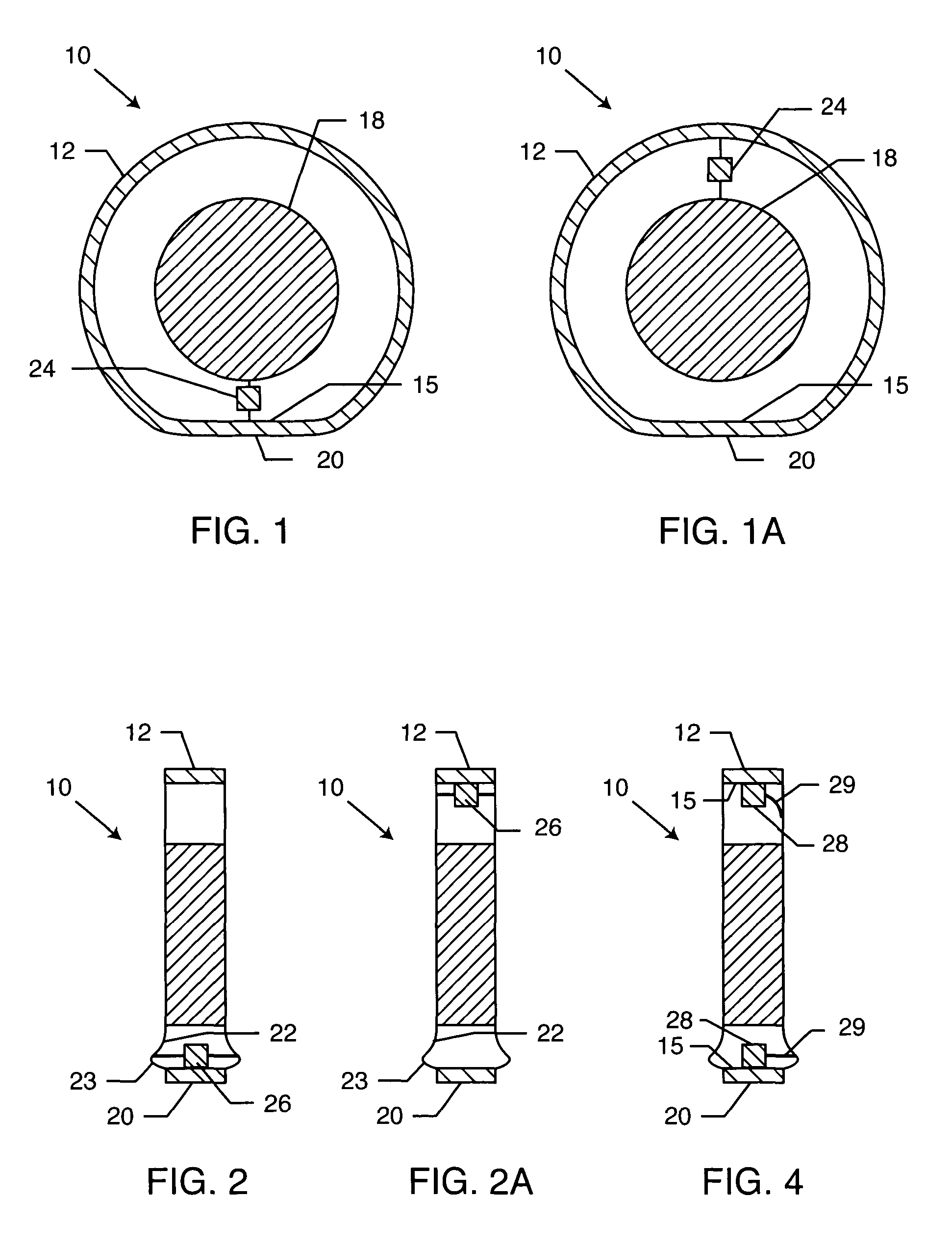
[0059] FIGS. 1 and 2 show a loaded vehicle tire 10 mounted on a rim 18 and its mechanical reciprocation induced by the tire 10 going from round to flat at the tire-to-road contact region 20. The following reciprocation motions are periodic (once per revolution)

[0060] as shown in FIG. 1, the shortening of the distance from the rim to the tire tread as the tire temporarily deflates when on the contact region; and

[0061] as shown in FIG. 2, on the tire shoulder just above the tread, the widening of the distance between the tire inner walls as each wall deflects (balloons) outward when on the contact region.

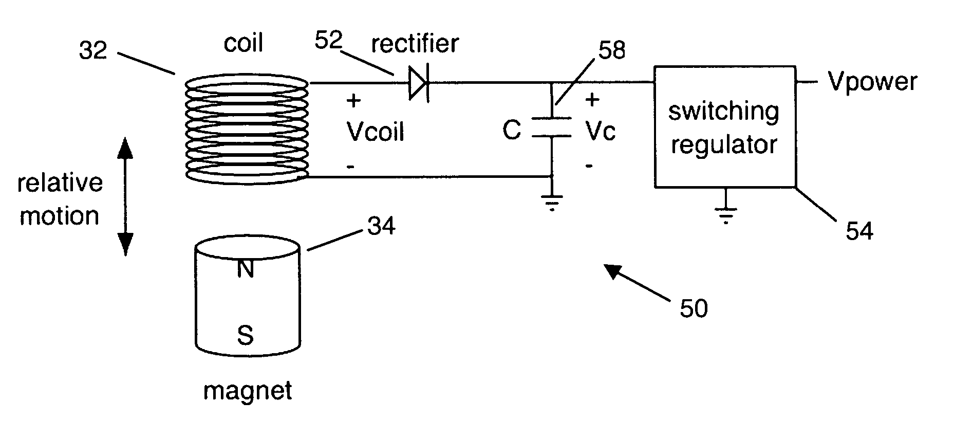
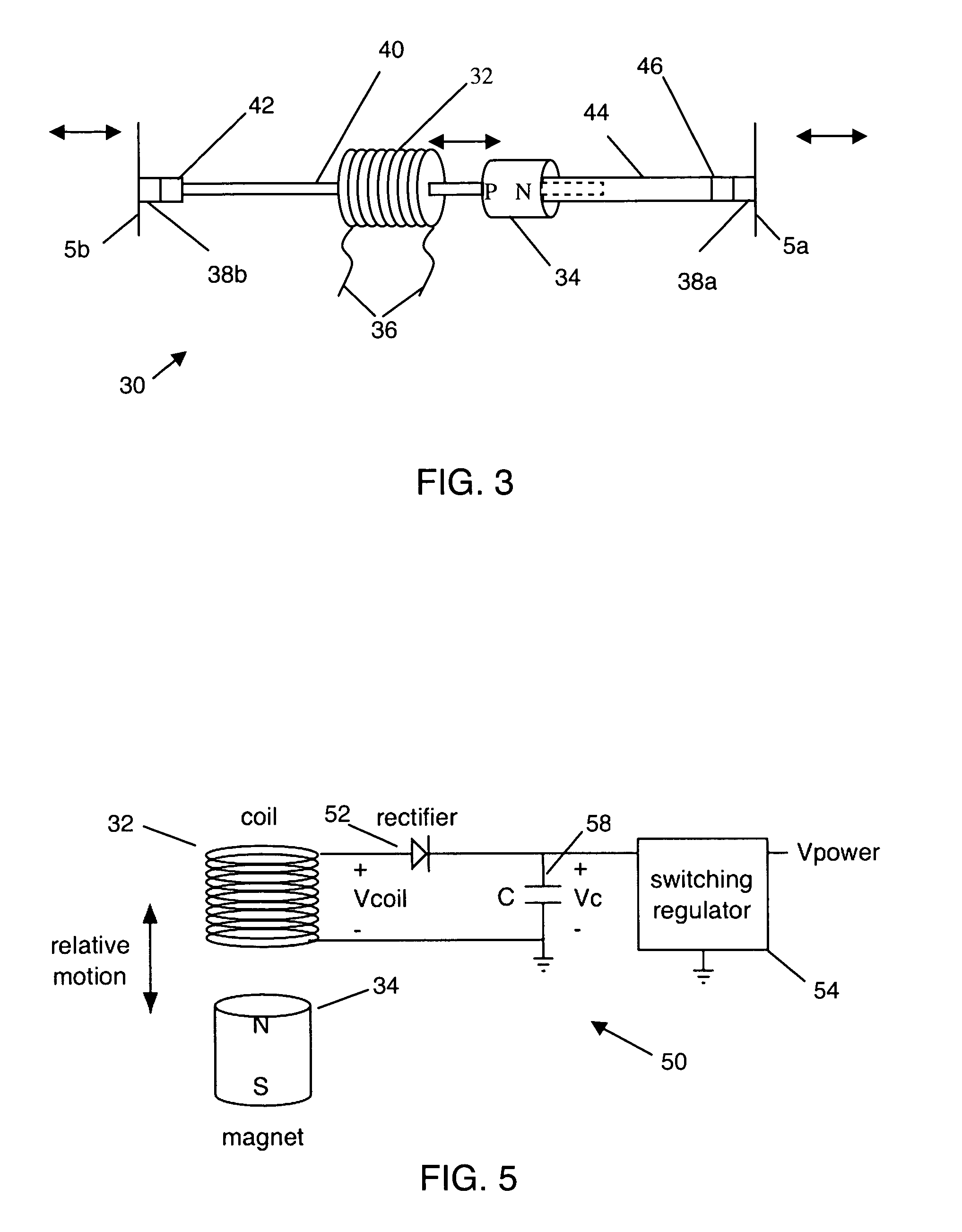
[0062] Both reciprocating motions are used to generate power by connecting an energy conversion device within the tire 10 to utilize the motions. A radial deflation generator 24 connects between the tire tread 12 inner surface 15 and the rim 18 as shown in FIGS. 1 and 1A. An inner wall deflection 26 generator connects between the two inner wall surfaces 22 of the tire 10 at shoulder 2...


PUM


Abstract

Energy for in-tire use is generated from the load induced reciprocating deflection of the tire inner walls above the tire-to-road contact patch adjacent to the shoulder of the tire. This energy is used to power in-tire monitoring electronics. For pulsatile energy generation with capacitive capture, the capacitor is optimally selected in real-time as a function of pulse width to maximize energy capture, or as a function of the pulse-captured energy. The resulting energy pulses are also used to measure the time duration of the contact patch from which the contact patch length is determined thus providing real-time tire geometry and, with tire pressure, real time tire load and, with temperature, tire air molar content. The loads on all tires provide real time vehicle mass and mass distribution. For electrical energy generation, magnet-coil, piezo-electric, and other power conversions are applicable. For non-electric energy generation, fluid bellows, rotary pump, and other power conversions are applicable. Further, run flat tires are designed with a cutout to accommodate and protect electronic devices mounted on an inner surface when running flat.

Description

[0001] This application claims the benefit of U.S. Provisional Application Serial No. 60 / 398,492 filed 25 Jul. 2002; 60 / 413,394 filed 24 Sep. 2002; 60 / 444,797 filed 3 Feb. 2003; 60 / 476,606 filed 7 Jun. 2003; and pending U.S. patent application Ser. No. 10 / 143,312, filed 10 May 2002, all of which are incorporated herein by reference in their entireties.[0002] 1. Field of the Invention[0003] The present invention relates generally to vehicle tires and to devices placed within the tires. More particularly, the present invention relates to apparatus and methods to generate renewable power within the tire to activate instrumentation placed within the tires. The generated power signals are also used to measure the length of the tire-to-road contact region and tire geometry that, with tire pressure, provides the tire load, the mass and center-of-mass of the vehicle, and other derived tire or vehicles values known in the field. The invention further relates to energy-optimal pulsed power ca...

Claims


Application Information

Patent Timeline
Patent Type & Authority Applications(United States)
IPC IPC(8): B60C23/04B60C23/06F01B19/04H02K7/18
CPCB60C23/041B60C23/0411H02K7/1846F01B19/04B60C23/064F03G7/08
Inventor WILSON, KITCHENER CLARK
Owner WILSON KITCHENER CLARK
Why Eureka
Try Eureka