Nitrogen rejection method and apparatus

a technology of nitrogen rejection and nitrogen, applied in lighting and heating apparatus, refrigeration machines, solidification, etc., to achieve the effect of facilitating the operation of downstream compressors or compressors

Inactive Publication Date: 2004-06-03
THE BOC GRP PLC
View PDF6 Cites 15 Cited by
  • Summary
  • Abstract
  • Description
  • Claims
  • Application Information

AI Technical Summary

Benefits of technology

0009] The method and apparatus according to the invention are able to be operated, if desired, at a constant liquid pump outlet pressure. This facilitates operation of a downstream compressor or compressors. Indeed, if the product is required at 40 bar and the outlet pressure of the liquid pump was set throughout the operating life of an apparatus according to the invention the reduction in product flow as a result of increasing nitrogen concentration in the natural gas may be catered for by a plural stage integrally geared product compressor fitted with adjustable inlet guide vanes and adjustable diffuser guide vanes. The external work performed by the feed expansion turbine is typically the generation of electrical power.
0010] In a preferred method according to the invention the operating pressure of the lower pressure rectification column is periodically increased in response to increases in the mole fraction of nitrogen in the pressurised feed gas stream. Accordingly, there is preferably a back pressure regulating valve associated with the lower pressure rectification column which is operable to increase the pressure in the lower pressure rectification column. An advantage of this arrangement is that at higher operating pressures of the lower pressure rectification column a stream of gas withdrawn from the lower pressure rectification column can be expanded with the performance of external work. A second expansion turbine may be provided for this purpose. The expansion of the gas from the lower pressure rectification column may be performed downstream of the passage of such gas through the main heat exchanger and may be employed to generate electrical power. Alternatively, the expansion in the second turbine of the gas stream from the lower pressure rectification column may be performed at cryogenic temperatures and may be employed to generate additional refrigeration for the method. For example, the second expansion turbine may be employed to provide refrigeration for a subcooler in which liquid streams flowing from the higher pressure rectification column to the lower pressure rectification column are subcooled. It is desirable to provide a first heater upstream of the first expansion turbine so as to preheat the feed gas stream. If the second turbine is positioned downstream of the main heat exchanger, there is preferably a second preheater intermediate of the main heat exchanger and the second turbine so as to preheat the gas stream to be expanded therein.

Problems solved by technology

Difficulties arise in providing a compressor or series of compressors that is able to operate efficiently when its inlet pressure varies within such a wide range of pressures.

Method used


Image

  • Nitrogen rejection method and apparatus
  • Nitrogen rejection method and apparatus
  • Nitrogen rejection method and apparatus

Examples


example 2

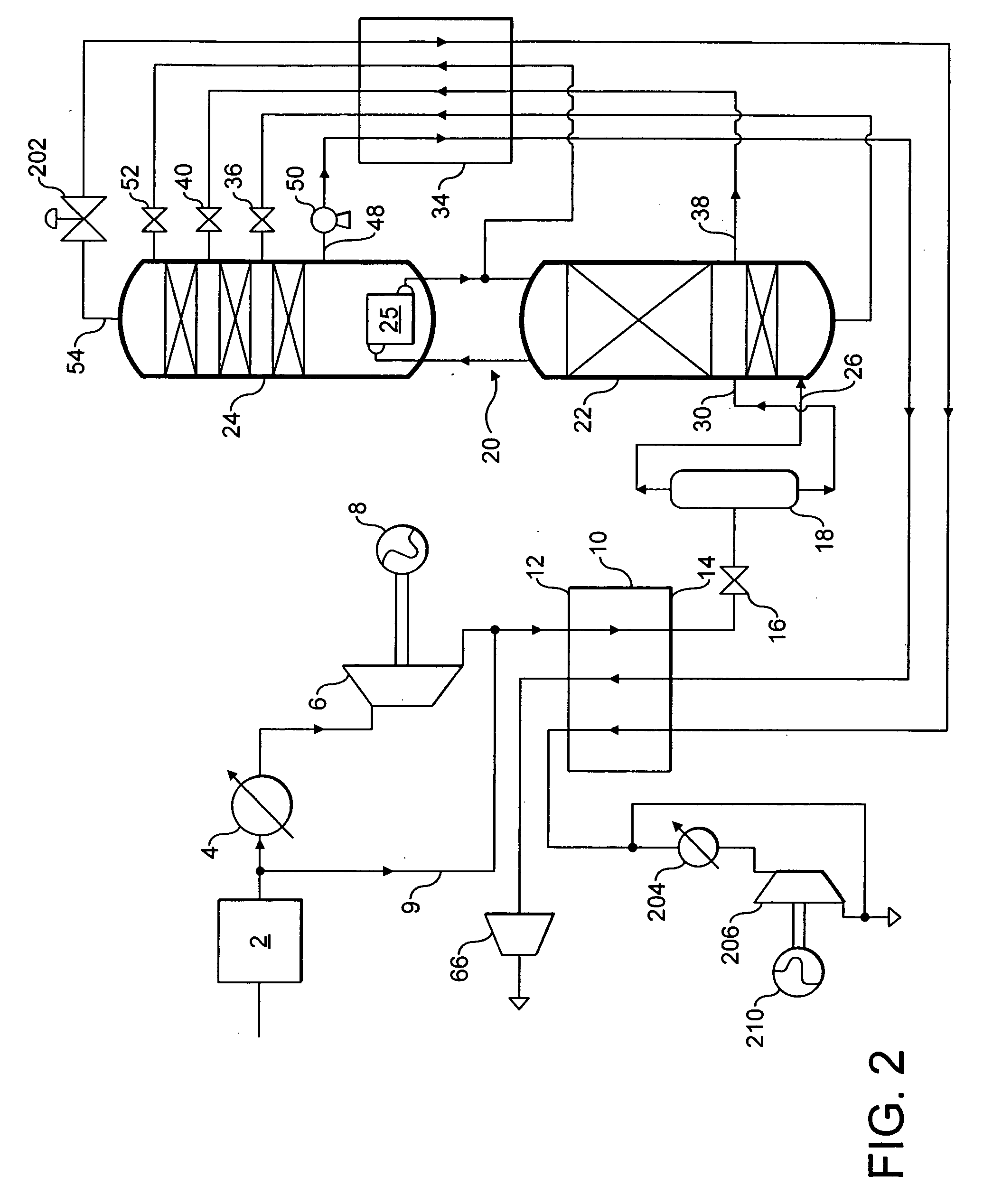
[0034] Referring to FIG. 2, operation of the expansion turbine 206 under the final operating conditions mentioned in FIG. 1 can generate additional power provided the operating pressure of the column 24 is raised. If the column 24 is operated at a pressure at its top of 2 bar, then the final operating conditions set out in Example 1 above are changed to:

3 Product methane flow = 6040.5 nm.sup.3 / hr Methane recovery = 99.67% Waste nitrogen flow = 3959.5 nm.sup.3 / hr Power generated by expansion turbine 206 = 68.4 kW

example 3

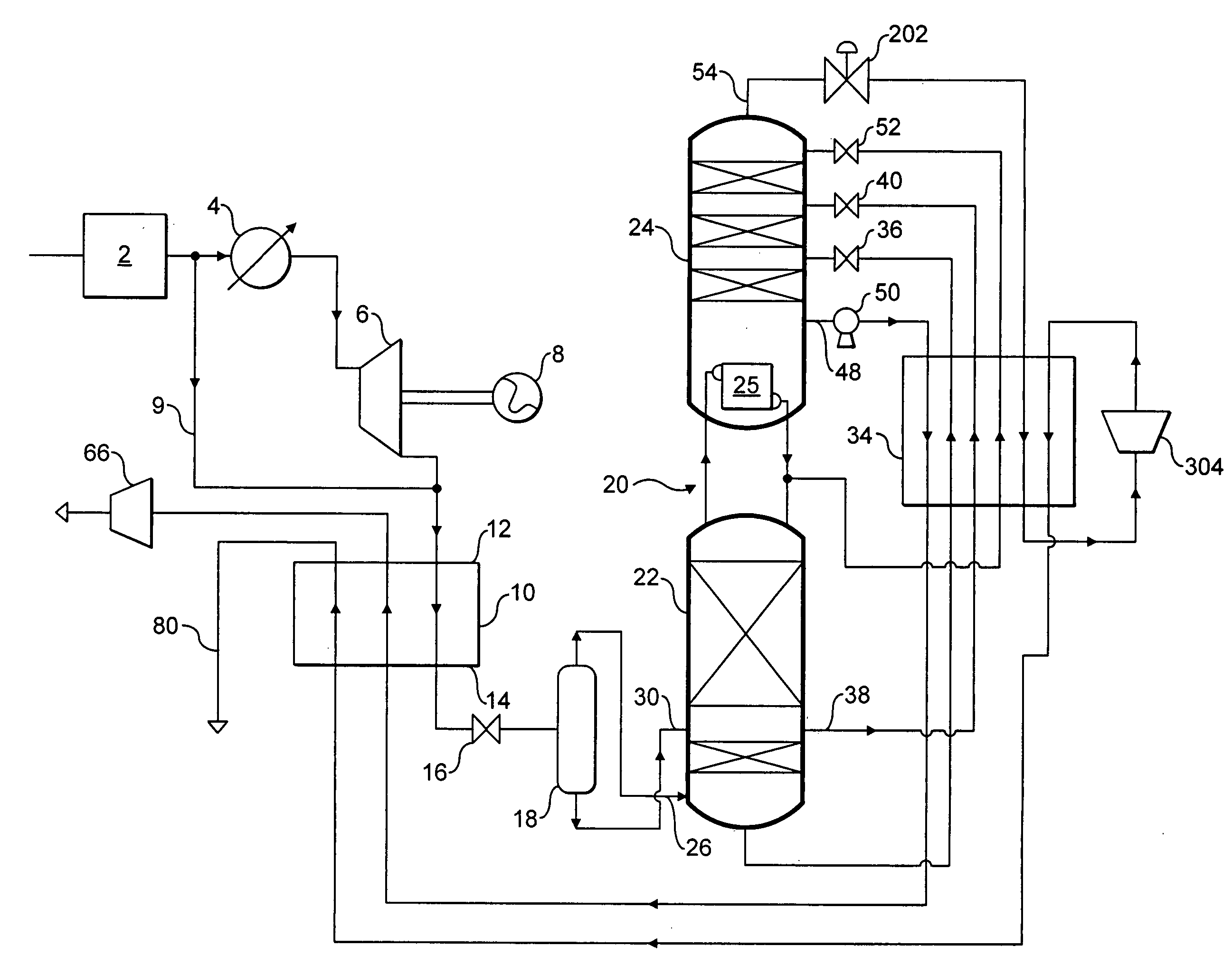
[0035] Referring to FIG. 3, the expansion turbine 304 produces refrigeration and creates sufficient additional reflux for the column 24 to be operated at elevated pressure. Thus, the waste nitrogen in the pipeline 80 can be produced at elevated pressure enabling it to be expanded with the production of power by an expansion turbine (not shown) analogous to the expansion turbine 206 shown in FIG. 2. Under the initial operating conditions specified in Example 1 but with a pressure at the top of the column 24 of 2 bar, the following flows and power recovery are achieved.

4 Product methane flow = 7903 nm.sup.3 / hr Methane recovery = 2097 nm.sup.3 / hr Waste nitrogen power generated = 7.5 kW

[0036] This power generation is in addition to the 112 kW generated by the expansion turbine 6 (see Example 1 above).


PUM


Abstract

Nitrogen is rejected from a pressurised feed gas stream comprising methane and nitrogen by cooling the feed gas stream in a main heat exchanger 10 and rectifying the cooled feed gas stream in a double rectification column 20 comprising a higher pressure rectification column 22, a lower pressure rectification column 24, and a condenser-reboiler 25 placing the higher pressure column 22 in heat exchange relationship with the lower pressure column 24. A pump 50 withdraws a methane product stream from the column 24. The methane product stream is pressurised by the pump 50 and is vaporised in the main heat exchanger 10. The pressurised feed gas stream is expanded with the performance of external work in an expansion turbine 6 upstream of the main heat exchanger 10.

Description

BACKGROUND TO INVENTION[0001] This invention relates to a method and apparatus for rejecting nitrogen from a feed gas stream comprising methane and nitrogen so as to form a methane product.[0002] It is known to extract natural gas from underground reservoirs. The natural gas often contains nitrogen. The nitrogen may be in part or totally derived from nitrogen which has been injected into the reservoir as part of an enhanced oil recovery (EOR) or enhanced gas recovery (EGR) operation. A feature of such operations is that the concentration of nitrogen in the natural gas tends to increase with the passage of time from about 5% by volume to about 60% by volume.[0003] U.S. Pa. No. 4,415,345 discloses a process for rejecting the nitrogen from the methane in a double rectification column operating at cryogenic temperatures. A double rectification column comprises a higher pressure rectification column, a lower pressure rectification column, and a condenser-reboiler placing the top of the h...

Claims


Application Information

Patent Timeline
Patent Type & Authority Applications(United States)
IPC IPC(8): F25J3/02
CPCF25J3/0209F25J3/0233F25J3/0257F25J2200/06F25J2200/72F25J2200/78Y10S62/927F25J2235/60F25J2240/02F25J2240/12F25J2240/44F25J2270/04F25J2280/02F25J2205/04
Inventor CLARE, STEPHEN ROGEROAKEY, JOHN DOUGLAS
Owner THE BOC GRP PLC
Why Eureka
Try Eureka