Optical information recording medium

a technology of optical information and recording medium, which is applied in the field of optical information recording medium, can solve the problems of reducing the recording sensitivity of the second information layer 24, and the inability to obtain the saturated signal amplitude in the second information layer, and achieves the effect of increasing the recording sensitivity of the second information layer 24

Inactive Publication Date: 2004-06-03
PANASONIC CORP
View PDF19 Cites 22 Cited by
  • Summary
  • Abstract
  • Description
  • Claims
  • Application Information

AI Technical Summary

Benefits of technology

0088] The thickness of the second recording layer 19 is preferably in a range of 6 nm to 20 nm so as to enhance the recording sensitivity of the second information layer 24. Even in this range, in the case where the second recording layer 19 is thick, a thermal effect on an adjacent region due to the diffusion of heat in an in-plane direction becomes large. Furthermore, in the case where the second recording layer 19 is thin, the reflectance of the second information layer 24 becomes small. Therefore, it is more preferable that the thickness of the second recording layer 19 is in a rang

Problems solved by technology

However, due to the loss by an optical system such as a lens, the power irradiated to the optical information recording medium beco

Method used


Image

  • Optical information recording medium
  • Optical information recording medium
  • Optical information recording medium

Examples


example 1

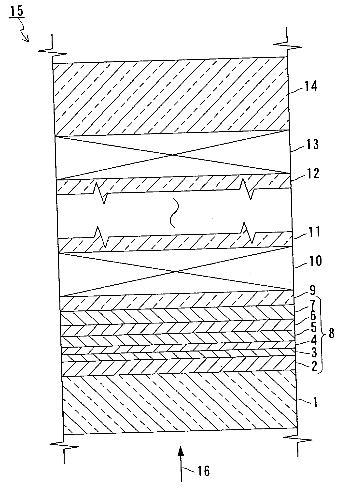
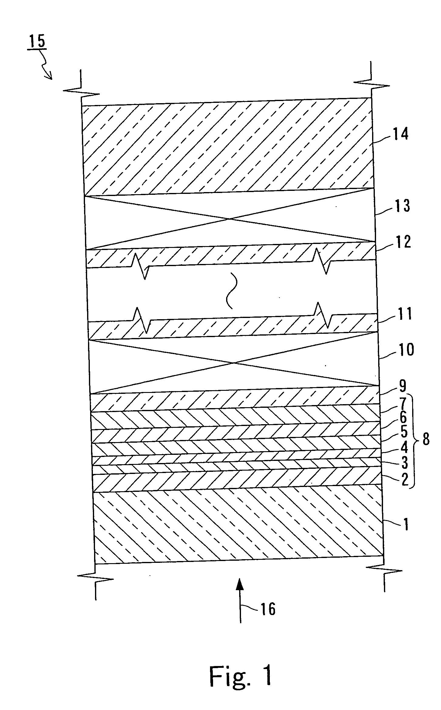
[0127] In Example 1, the first information layer 8 of the recording medium 15 shown in FIG. 1 was produced. The relationship between the refractive index nil, extinction coefficient k1 and thickness d1 of the transmittance adjusting layer 7, and the transmittance and reflectance of the first information layer 8 was checked. More specifically, samples were produced, each having the transparent layer 1 and the first information layer 8 including the transmittance adjusting layer 7 with varying material and thickness.

[0128] The samples were produced as follows. First, a polycarbonate substrate (diameter: 120 mm; thickness: 1100 .mu.m) was prepared as the substrate 14. Then, the transmittance adjusting layer 7 (thickness: 2 nm to 140 nm), an Ag--Pd--Cu layer (thickness: 10 nm) as the reflection layer 6, a Ge--Si--N layer (thickness: 10 nm) as the upper side protection layer 5, a Ge.sub.8Sb.sub.2Te.sub.11 layer (thickness: 6 nm) as the recording layer 4, a Ge--Si--N layer (thickness: 5 n...

example 2

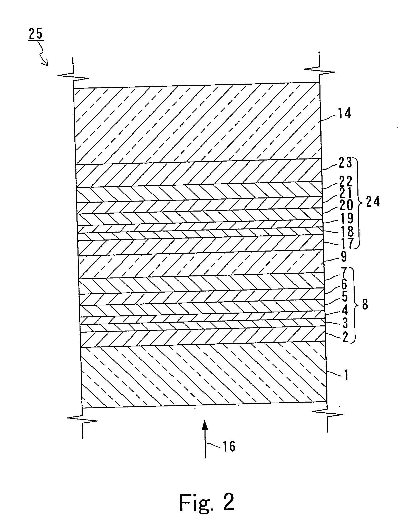
[0134] In Example 2, the relationship between the characteristics of the first information layer 8, and the material and thickness of the recording layer 4 was checked. More specifically, samples were produced in which the substrate 14, the first information layer 8 including the recording layer 4 with varying thickness, and the transparent layer 1 were stacked. Regarding the samples thus produced, the first information layer 8 was measured for an erasure ratio, a carrier to noise ratio (CNR), a reflectance and a transmittance.

[0135] The samples were produced as follows. First, a polycarbonate substrate (diameter: 120 mm; thickness: 1100 .mu.m) with guide grooves for guiding the laser beam 16 was prepared as the substrate 14. Then, a TiO.sub.2 layer (thickness: 15 nm) as the transmittance adjusting layer 7, an Ag--Pd--Cu layer (thickness: 5 nm to 10 nm) as the reflection layer 6, a Ge--Si--N layer (thickness: 10 nm) as the upper side protection layer 5, a Ge.sub.8Sb.sub.2Te.sub.11 l...

example 3

[0140] In Example 3, the relationship between the characteristics of the first information layer 8 and the thickness d2 of the reflection layer 6 was checked. More specifically, samples were produced in which the substrate 14, the first information layer 8 including the reflection layer 6 with varying thickness, and the transparent layer 1 were stacked. Regarding the samples thus produced, the first information layer 8 was measured for a CNR, an erasure ratio, a reflectance and a transmittance.

[0141] The samples were produced as follows. First, a polycarbonate substrate (diameter: 120 mm; thickness: 1100 .mu.m) with guide grooves for guiding the laser beam 16 was prepared as the substrate 14. Then, a TiO.sub.2 layer (thickness: 15 nm) as the transmittance adjusting layer 7, an Ag--Pd--Cu layer (thickness: 2 nm to 20 nm) as the reflection layer 6, a Ge--Si--N layer (thickness: 10 nm) as the upper side protection layer 5, a Ge.sub.8Sb.sub.2Te.sub.11 layer (thickness: 6 nm) as the reco...


PUM


Abstract

An optical information recording medium for recording and reproducing information by irradiation with a laser beam having a wavelength lambda of 450 nm or less includes a substrate 14 and a plurality of information layers formed on the substrate. A first information layer 8 closest to an incident side of the laser beam among the plurality of information layers includes a recording layer 4, a reflection layer 6 and a transmittance adjusting layer 7. A transmittance Tc1 (%) of the first information layer 8 at the wavelength lambda in a case of the recording layer 4 in a crystal phase and a transmittance Ta1 (%) of the first information layer 8 at the wavelength lambda in a case of the recording layer 4 in an amorphous phase satisfy 46<Tc1 and 46<Ta1. Furthermore, a refractive index n1 and an extinction coefficient k1 of the transmittance adjusting layer 7 at the wavelength lambda, and a refractive index n2 and an extinction coefficient k2 of the reflection layer 6 at the wavelength lambda satisfy 1.5<=(n1-n2) and 1.5<=(k2-k1).

Description

[0001] The present invention relates to an optical information recording medium that includes a plurality of information layers and records, erases, rewrites or reproduces information optically by irradiation with a laser beam.[0002] As an optical information recording medium that records, erases, rewrites or reproduces information using a laser beam, there is a phase-change type optical information recording medium. The phase-change type optical information recording medium uses a phenomenon in which its recording layer is changed reversibly between a crystal phase and an amorphous phase, for recording, erasing and rewriting information. Generally, in the case of recording information, a recording layer is melted by irradiation with a laser beam having a high power (recording power), followed by rapid cooling, whereby an irradiated portion is changed to an amorphous phase to record information. On the other hand, in the case of erasing information, a recording layer is raised in te...

Claims


Application Information

Patent Timeline
IPC IPC(8): G11B7/2403G11B7/24038G11B7/24067G11B7/243G11B7/253G11B7/2534G11B7/254G11B7/2542G11B7/257G11B7/258G11B7/2585G11B7/259G11B7/2595
CPCG11B7/2403G11B2007/24316G11B7/24067G11B7/243G11B7/252G11B7/2534G11B7/2542G11B7/257G11B7/258G11B7/2585G11B7/259G11B7/2595G11B2007/24312G11B2007/24314G11B7/24038
Inventor NISHIHARA, TAKASHIKOJIMA, RIEYAMADA, NOBORU
Owner PANASONIC CORP
Why Eureka
Try Eureka