Structure and process for production thereof

a technology of high-density recording and structure, applied in the field of structure for high-density recording, can solve the problems of insufficient recording capability, insufficient magnetic recording medium sensitivity to external magnetic field for recording, and disadvantages of magnetic recording, so as to improve the recording sensitivity of magnetic recording medium and maintain thermal fluctuation resistance

Inactive Publication Date: 2007-11-08
CANON KK
View PDF13 Cites 5 Cited by
  • Summary
  • Abstract
  • Description
  • Claims
  • Application Information

AI Technical Summary

Benefits of technology

[0019]The present invention enables improvement of the recording sensitivity of the magnetic recording medium with the thermal fluctuation resistance maintained.

Problems solved by technology

This produces a superparamagnetic effect (thermal fluctuation) to cause dissipation of magnetic record disadvantageously.
This lowers the sensitivity of the magnetic recording medium to an external magnetic field for the recording.
In particular, a higher recording density and a higher data transfer rate demanded in recent years will limit the maximum intensity of the magnetic field generated by a recording head to make insufficient the recording capability.
However, any of known techniques does not satisfy all of the above requirements.

Method used


Image

  • Structure and process for production thereof
  • Structure and process for production thereof
  • Structure and process for production thereof

Examples


example 1

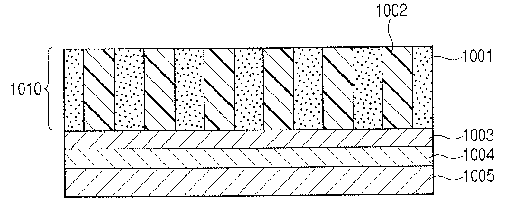
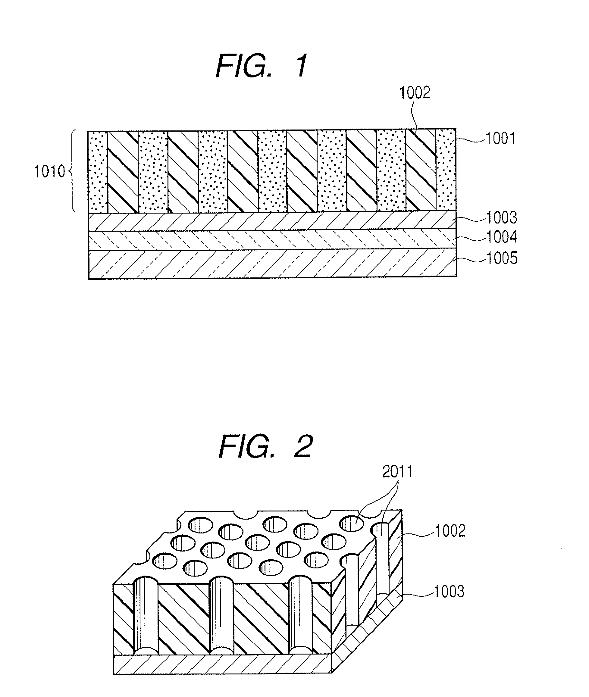
[0070]A porous member having pores of 20 nm diameter at pore intervals of 30 nm and an aspect ratio of 1 is prepared as described below.

[0071]A (001)-oriented MgO layer (20 nm thick) is prepared on a substrate. On this MgO layer, a thin Pt film of 10 nm thick is formed by magnetron sputtering. On this thin Pt film, a Ti film of 1 nm thick is formed. This Ti film serves to prevent exfoliation of the film in the later anodization process. Thereon a AlZr alloy film of 20 nm thick, and a AlW film of 80 nm thick are formed successively. The Zr content in the AlZr alloy film, and the W content in the AlW alloy film are preliminarily determined of separate single films by fluorescence X-ray analysis (XRF), and are found to be 10 atom % and 10 atom % respectively. The prepared film is anodized in an aqueous 1 mol / L sulfuric acid at a bath temperature of 3° C. by application of a voltage of 12 V. After the anodization, a pore-widening treatment is conducted by immersion in an aqueous 2-wt % ...

example 2

[0078]A porous member similar to the one of Example 1 is prepared.

[0079]The sputtering is conducted nearly in the same manner as in Example 1, except that the plate-shaped filter and the substrate bias conditions are changed as below in order to control formation of the first crystal particles and the second crystal particles.

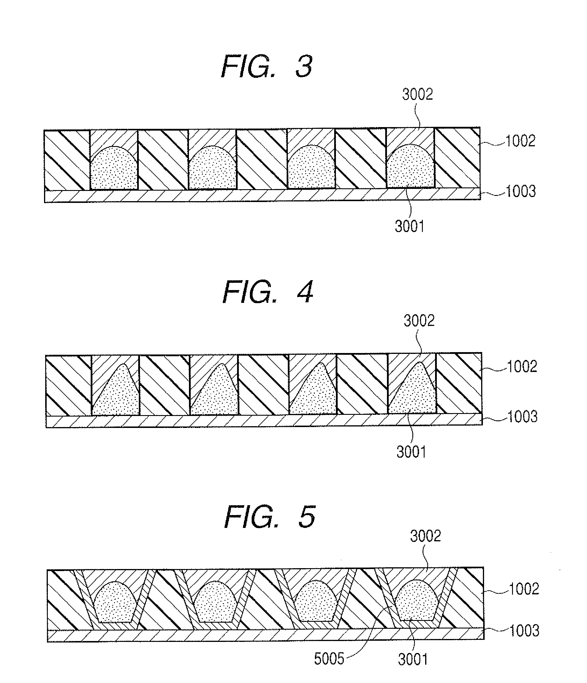
[0080]In the first sputtering, the filter is inclined by an angle of 5° relative to the substrate. Thereby, the holes through the filter are also inclined by 5° relative to the substrate to change slightly the projection direction of the sputtered particles from the direction perpendicular to the substrate. In this first sputtering, the bias voltage of −40 V is applied to the substrate. Crystal particles 3001 are formed eccentrically to be shifted from the center axes of the pores perpendicular to the substrate as illustrated in FIG. 4. The first crystal particles are formed to a height of 10 nm from the bottom face of the pores. In the subsequent second sputte...

example 3

[0084]In this example, an orientation-controlling layer is provided on the respective pore walls.

[0085]A porous member is provided, as illustrated in FIG. 5, in which the pores are arranged at intervals of 30 nm, the pore diameter at the pore top is 28 nm, and the pore diameter at the bottom is smaller than at the pore top, and the aspect ratio of the pore is 1.

[0086]A Si substrate is employed. A (001)-oriented MgO layer (20 nm thick) is prepared on the Si substrate. On this MgO layer, a thin Pt film of 10 nm thick is formed by magnetron sputtering. On the thin Pt film, a Ti film of 1 nm thick is formed. Thereon a AlZr alloy film of 20 nm thick is formed in which the amount of the added Zr is reduced gradually from the substrate side toward the surface, and a AlW film of 80 nm thick are formed further thereon. The Zr content in the AlZr alloy and the W content in the AlW alloy are preliminarily determined of separate films by fluorescence X-ray analysis (XRF), the content being 10 a...


PUM

PropertyMeasurementUnit
diameteraaaaaaaaaa
diameteraaaaaaaaaa
diameteraaaaaaaaaa

Abstract

A structure has a substrate and a layer containing a magnetic material dispersed in a nonmagnetic material, the magnetic material being comprised of first crystal particles having an easy magnetization axis crytsllographically oriented in the direction of the normal line of the substrate and forming columns perpendicular to the substrate and second crystal particles having a crystallographic orientation in a direction different from the direction of the crystallographic orientation in the first crystal particles, and the ratio of the second crystal particles to the entire crystal particles in the columns ranging from 10% to 50% by weight.

Description

BACKGROUND OF THE INVENTION[0001]1. Field of the Invention[0002]The present invention relates to a structure for high-density recording, and a process for producing the structure.[0003]2. Description of the Related Art[0004]Remarkable increase of the amount of information in recent years necessitates a higher recording density and a higher recording capacity for magnetic recording devices like a hard disk device (HDD). For the high recording density, magnetic particles contained in the recording layer should be micronized. However, the micronization of magnetic particles makes significant the thermal energy retained in the particle relative to the magnetic energy. This produces a superparamagnetic effect (thermal fluctuation) to cause dissipation of magnetic record disadvantageously. To stabilize the magnetic record against the thermal fluctuation, materials are being developed which have a higher magnetic anisotropy constant (Ku).[0005]The magnetic recording medium containing a hig...

Claims


Application Information

Patent Timeline
Patent Type & Authority Applications(United States)
IPC IPC(8): G11B5/65B05D5/12C23C14/32B32B15/00
CPCC23C14/042C23C14/046C23C14/165C23C14/345Y10T428/32C23C14/588G11B5/851G11B5/855C23C14/5873
Inventor ICHIHARA, SHIGERUDEN, TORU
Owner CANON KK
Why Eureka
Try Eureka