Bicycle cable brake control line

a technology of brake control line and bicycle cable, which is applied in the direction of bicycle brakes, steering devices, cycle equipment, etc., can solve the problems of inability to manipulate, parts of the inextensible core to be pulled out, and inability to control the brak

Inactive Publication Date: 2004-06-17
BEARCORP
View PDF3 Cites 12 Cited by
  • Summary
  • Abstract
  • Description
  • Claims
  • Application Information

AI Technical Summary

Problems solved by technology

Prior to this time such a manipulation was not possible since the bicycle brake cables extending from the hand brake controls on the handlebars to the brake calipers of the brakes on the front and rear wheels of a bicycle would permit only limited rotation of the steering assembly relative to the frame to an arc of far less than 360 degrees.
However, twisting of the handlebars relative to the bicycle fr

Method used


Image

  • Bicycle cable brake control line
  • Bicycle cable brake control line
  • Bicycle cable brake control line

Examples


Embodiment Construction

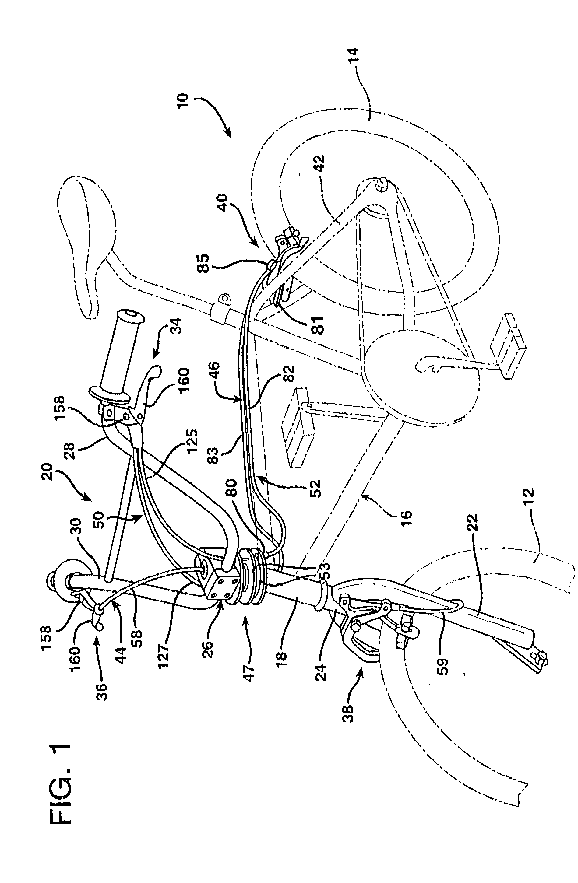
[0039] FIG. 1 illustrates a bicycle 10 having the usual front wheel 12 and real wheel 14 which support a rigid, tubular steel or aluminum frame 16. The frame 16 is equipped with a hollow, cylindrical, annular bicycle frame head tube 18 at its forward end and a rear wheel fork 42 at its rear end.

[0040] The bicycle 10, like all bicycles, includes a front wheel steering assembly indicated generally at 20. The front wheel steering assembly 20 includes the front wheel 12, a front wheel fork 22, a steering tube 24, a handlebar stem 26, and a set of handlebars 28 and 30. The steering tube 24 is located atop the front wheel fork 22 and projects upwardly through the head tube 18 of the frame 16. The upper portion of the steering tube 24 that protrudes into the head tube 18 is captured within the grip of the stem 26. The stem 26 also carries the handle bars 28 and 30.

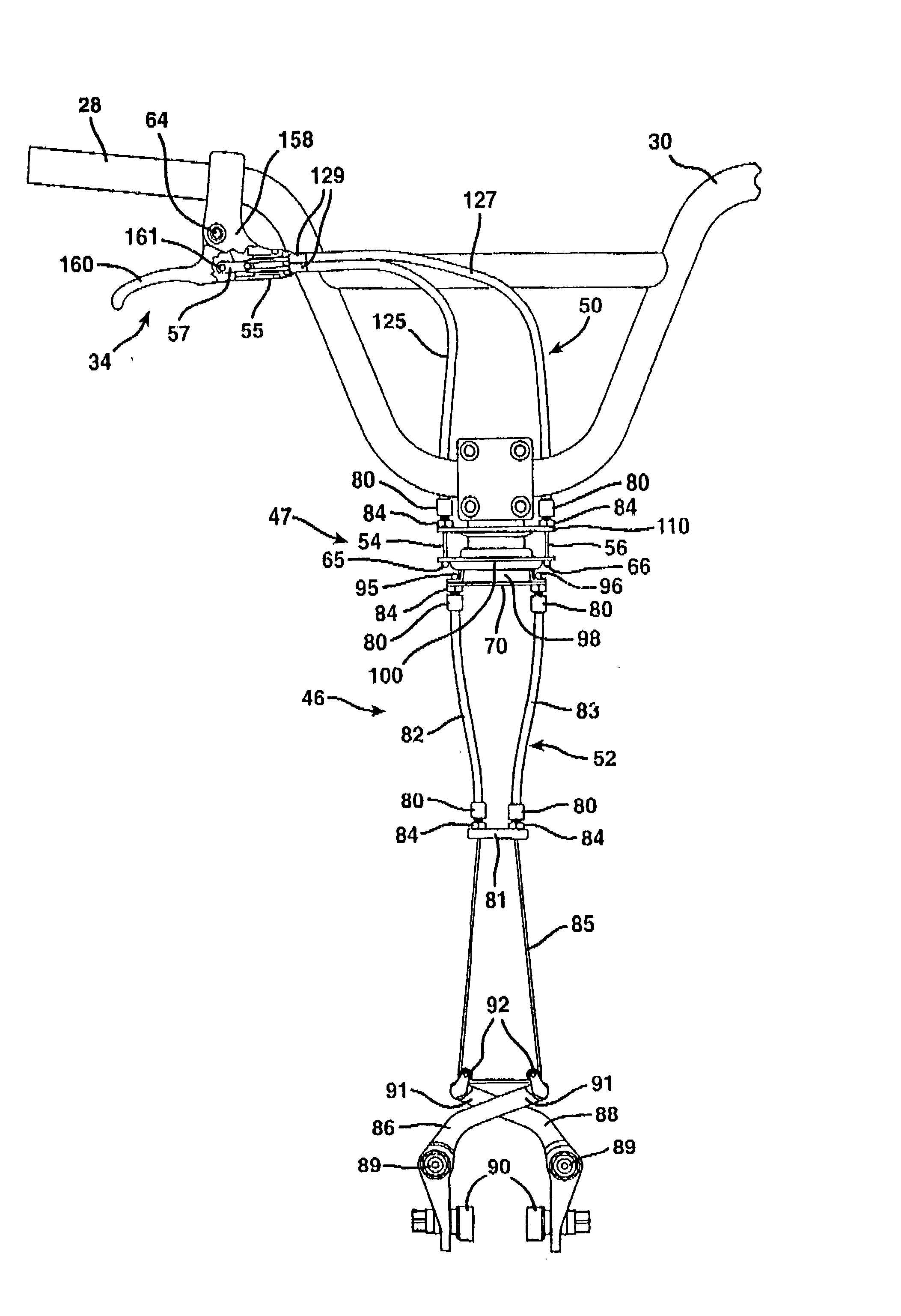
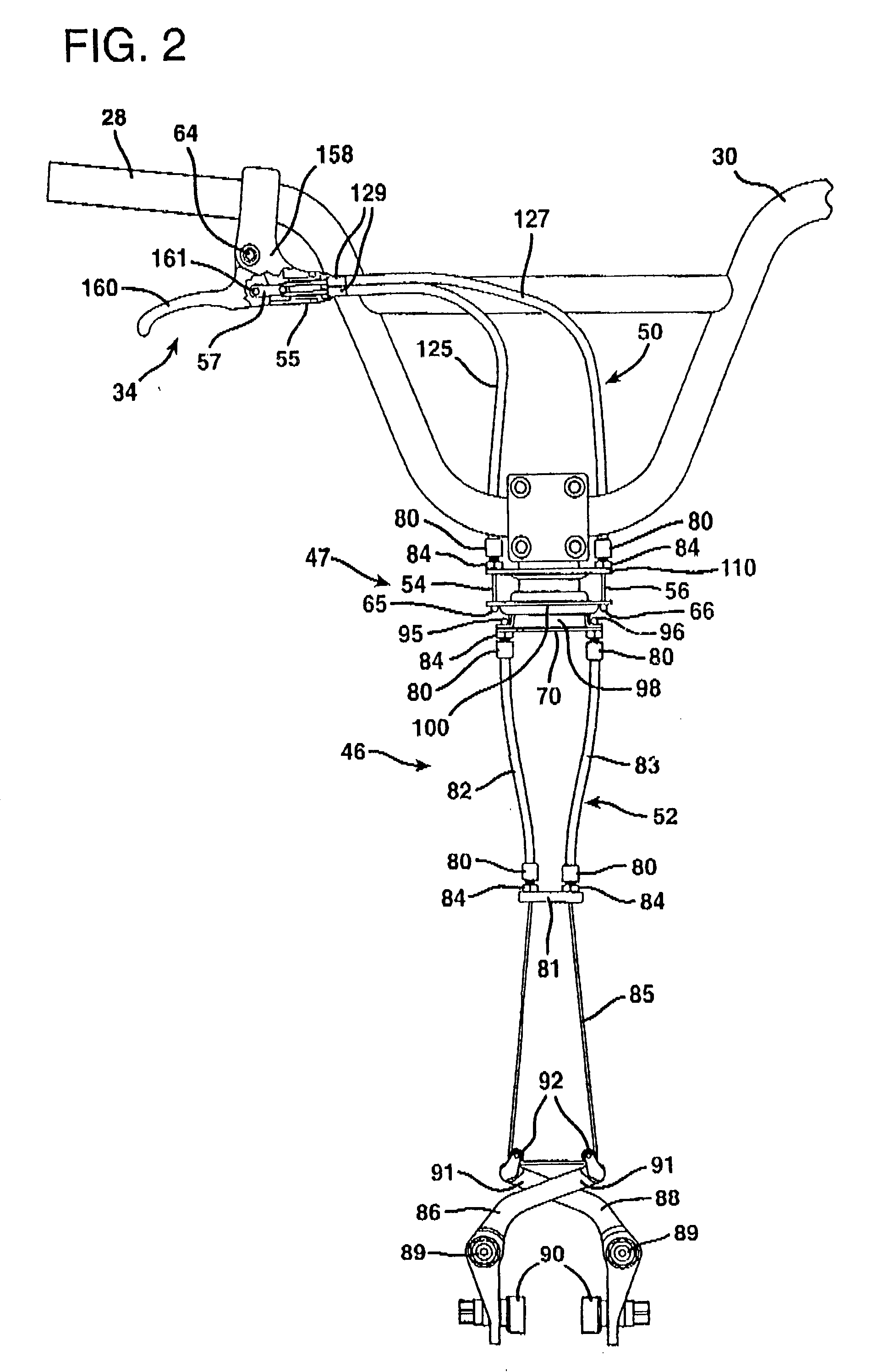
[0041] A rear wheel brake control 34 and a front wheel brake control 36 are respectively mounted on the handlebars 28 and 30 in...


PUM


Abstract

A single rear bicycle brake control cable core is employed to operate the rear brake of a freestyle bicycle that employs a rotatable coupling that allows the handlebars, front wheel, and front wheel fork of a bicycle to be rotated through a complete revolution about the axis of the head tube of the bicycle frame. The single brake control cable core is looped about a roller which may be a pulley attached to the cable-engaging end of the handlebar-mounted rear brake lever, so that the point of contact between the control cable loop relative to the brake lever is not fixed. Cable sheaths surround portions of the cable core and are seated in a cable segment connector that in turn is rotatably mounted in a cable coupler attached to a handlebar-mounted brake lever assembly body. The coupler rotates about its own axis to maintain the unsheathed, proximal portions of the loop adjacent the pulley in coplanar alignment with the pulley. The brake lever rotates relative to the brake lever assembly body so as to move the pulley closer to or further from the cable coupler. Because the control cable loop passes about the pulley, tension on the cable brake line allows the gyroscopic system to self-adjust the balance of its bearing unit. Preferably, a toggle link is provided between the cable-engaging end of the brake lever and the cable core loop. The pulley is mounted at the end of the toggle link, remote from the brake lever.

Description

[0001] 1. Field of the Invention[0002] The present invention relates to a bicycle brake cable system operated by a brake control lever mounted on a bicycle handlebar in a bicycle in which the handlebars and front wheel of the bicycle are freely rotatable relative to the bicycle frame.[0003] 2. Description of the Prior Art[0004] A conventional bicycle employs a frame upon which the seat, rear wheel, pedals, and chain drive transmission mechanism are mounted, and a steering assembly that can be turned relative to the frame. The major components of a bicycle steering assembly include a front wheel, a front wheel fork, a steering tube, a handlebar stem, and a set of handlebars. The steering assembly can be turned at an angle relative to the frame about an axis of rotation extending along the center of the steering tube of the steering assembly, which is also the center of the head tube of the frame. The steering tube is mounting coaxially within the head tube and turns relative thereto ...

Claims


Application Information

Patent Timeline
IPC IPC(8): B60T11/04B62K21/18B62L3/02
CPCB60T11/043B62L3/02B62K21/18B60T11/046B62J11/13
Inventor COTSONAS, CHRISTOPHER A.
Owner BEARCORP
Why Eureka
Try Eureka