Engine starting apparatus

a technology of engine starting and starting gear, which is applied in the direction of engine starting, electrical control, exhaust treatment electric control, etc., can solve the problems of increased cylinder pressure, increased fuel remaining in the intake port, and insufficient atomization of fuel, so as to achieve further reduction of emissions and fuel injection.

Inactive Publication Date: 2004-07-01
DENSO CORP
View PDF16 Cites 52 Cited by
  • Summary
  • Abstract
  • Description
  • Claims
  • Application Information

AI Technical Summary

Benefits of technology

0084] In the engine starting apparatus, when the speed of the engine is higher than the predetermined speed, the amount of fuel injection is redu

Problems solved by technology

However, when the engine is being started by the DC motor, as the engine starting speed (cranking rpm) is low, and the pressure of intake air being drawn into the cylinder is therefore low, fuel is not sufficiently atomized and the amount of fuel remaining in the intake port increases.
Furthermore, at a low engine speed, the cylinder pressure is low even when compressed by the piston, and the amount of unatomized fuel remaining in the cylinder also increases.
In particular, when a catalyst is in an inactive

Method used


Image

  • Engine starting apparatus
  • Engine starting apparatus
  • Engine starting apparatus

Examples


embodiment 1

[0141] (Effect of Embodiment 1)

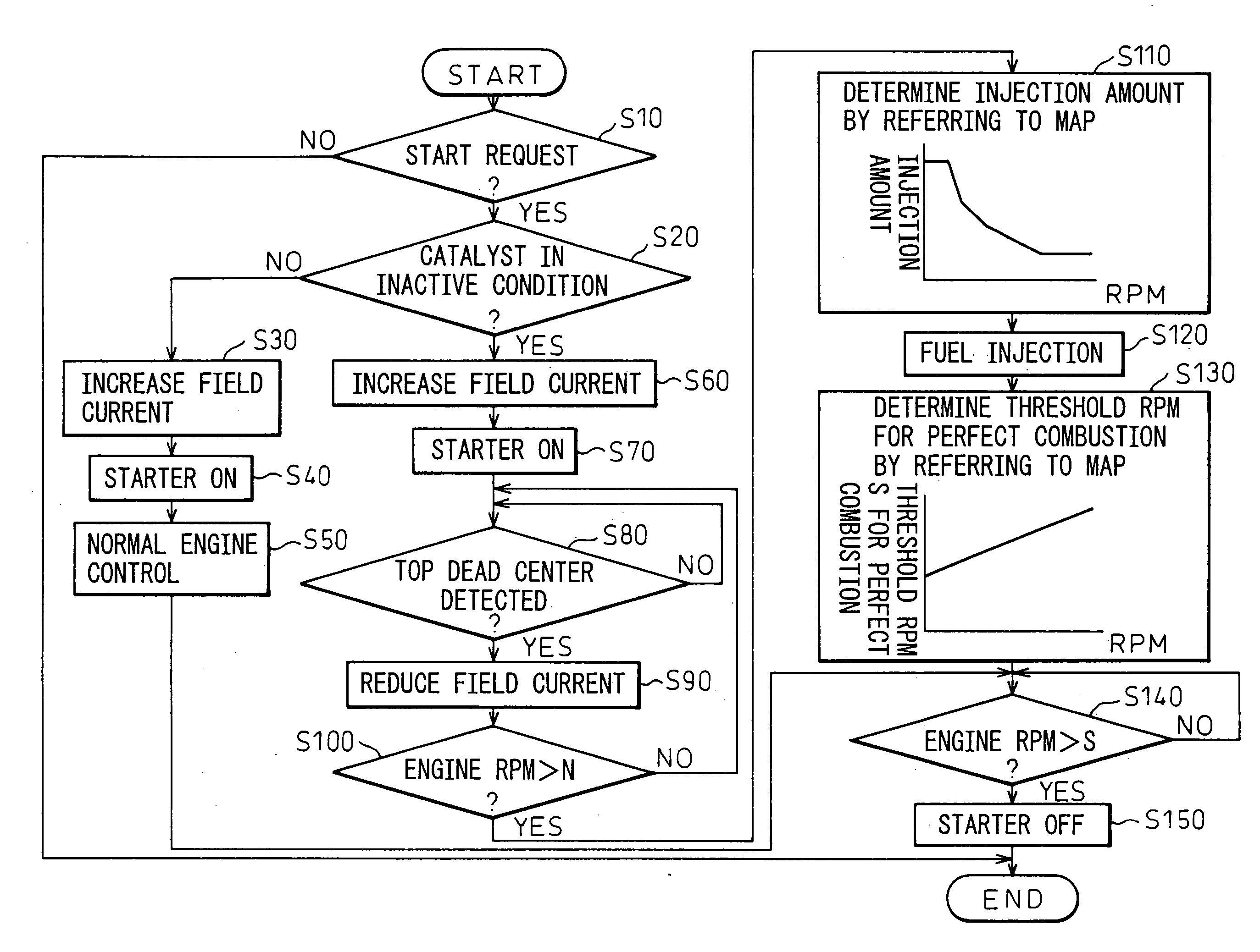
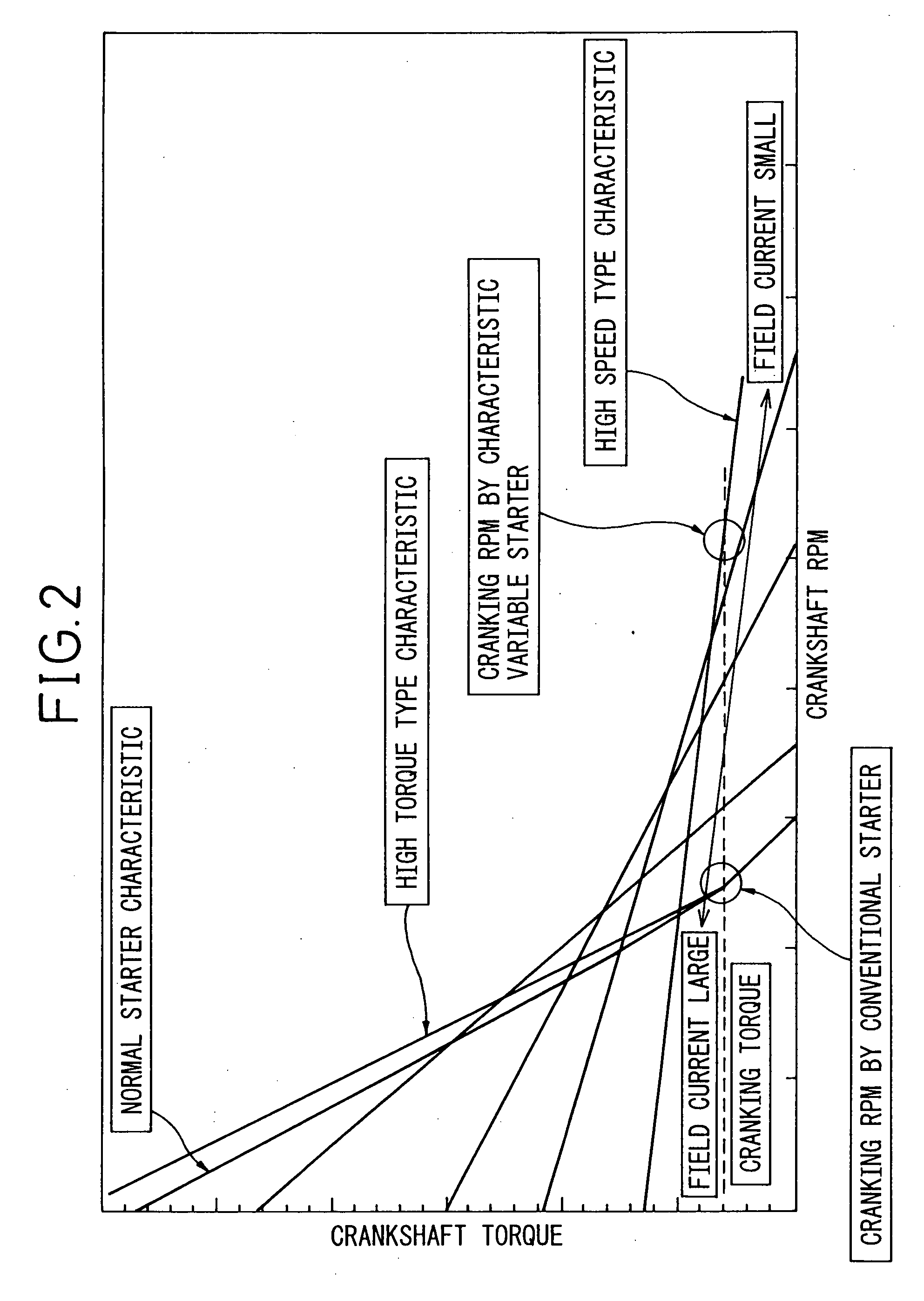
[0142] According to the present embodiment, when the catalyst is in an inactive condition, first, the engine is driven by controlling the output characteristic of the starter 1 to the high torque type (by increasing the field current), as shown in FIG. 4(a), and then, after top dead center is reached in any one of the cylinders, the output characteristic of the starter 1 is controlled to the high speed type by reducing the field current of the motor, thereby making it possible to properly drive the engine at high speed. As a result, as the engine rpm during cranking rises compared with the normal case (the case where the catalyst is in an active condition), as shown in FIG. 4(b), the amount of fuel remaining in the intake port and the cylinder decreases, and the injected fuel properly contributes to combustion. Accordingly, even when the catalyst is in an inactive condition (the purification performance is low), emissions (HC) emitted into the atmosphe...

embodiment 2

[0145] (Embodiment 2)

[0146] FIG. 5 is a flowchart illustrating the operation of the engine starting apparatus A.

[0147] In this embodiment, steps 80 / 90 and 100A are performed instead of the steps 80 to 100 shown in the flowchart described in the first embodiment. Otherwise, the process (steps 10 to 70 and 110 to 150) is the same as that of the first embodiment (the description will not be repeated here).

[0148] Details of the steps 80 / 90 and 100A will be described below.

[0149] Step 80 / 90: The field current of the motor is reduced compared with the normal case (the case where the catalyst is in a normal condition). More specifically, the field current is determined from the current engine rpm or starter rpm by referring to a map.

[0150] Step 100A: Decision is made as to whether or not intake manifold pressure is either equal to or higher than a predetermined value p. If the intake manifold pressure is higher than the predetermined value p (the result of the decision is NO), the process ...

embodiment 3

[0155] (Embodiment 3)

[0156] FIG. 6 is a flowchart illustrating the operation of the engine starting apparatus A.

[0157] This embodiment concerns an example, in which control of the reduction of the field current is stopped and is changed to the normal engine control.

[0158] The details of the control according to this embodiment will be described below with reference to the flowchart.

[0159] Steps 10 to 70: Same as the corresponding steps in the first embodiment (refer to the description of the first embodiment).

[0160] Step 80: The field current of the motor is reduced compared with that in the normal condition (that is, when the catalyst is in an active condition). More specifically, the field current is determined from the current engine rpm or starter rpm by referring to a map.

[0161] Step 90: The state of charge of the battery 10 is checked. If the state of charge is low (the result of the decision is NO), the field current reducing control is stopped, and the process proceeds to st...


PUM


Abstract

When starting an engine, it is judged whether a catalyst is in an inactive condition or not and, if it is judged that the catalyst is in an inactive condition, the motor field current is reduced to control the output characteristic of the starter to a high-speed type, thus enabling the engine to be driven at high speed. As the engine rpm during driving rises compared with the normal case (the case where the catalyst is in an active condition), the amount of fuel remaining in the intake port and the cylinder decreases, and the injected fuel properly contributes to combustion. Accordingly, even when the catalyst is in an inactive condition, emissions (of HC) emitted into the atmosphere can be reduced.

Description

[0001] The present invention relates to an engine starting apparatus for starting an engine at high speed (rpm) when a catalyst is in an inactive condition.BACKGROUND OF INVENTION[0002] Traditionally, series-wound DC motors, in which a field coil is connected in series with an armature coil, have often been employed as starter motors in engine starting apparatuses (refer to Japanese Unexamined Patent Publication No. 2000-125579). The output of this type of DC motor is determined based on the engine cranking torque, the lowest rotational speed capable of starting the engine, etc. so that a sufficient rotational speed can be obtained even in the wintertime (under extremely low temperature conditions).[0003] However, when the engine is being started by the DC motor, as the engine starting speed (cranking rpm) is low, and the pressure of intake air being drawn into the cylinder is therefore low, fuel is not sufficiently atomized and the amount of fuel remaining in the intake port increa...

Claims


Application Information

Patent Timeline
IPC IPC(8): F01N3/20F01N3/24F02N15/00F01N11/00F02D17/00F02D29/02F02D41/02F02D41/04F02D41/06F02D45/00F02N11/08
CPCF01N11/002F01N2550/02F02D41/0235F02N11/006F02N2300/102F02N2200/023F02N2200/024F02N2200/026F02N11/08
Inventor KAMIYA, MASARUKATO, AKIRAOSADA, MASAHIKO
Owner DENSO CORP
Why Eureka
Try Eureka