Electron beam source, electron optical apparatus using such beam source and method of operating an electron beam source

a beam source and electron beam technology, applied in the field of electron beam sources, can solve the problems of reducing the stability of the beam current, the field emission source is also insufficient with respect to the maximum beam current, and the field emission source requires ultra-high operation

Inactive Publication Date: 2004-07-01
CARL ZEISS SMT GMBH
View PDF14 Cites 25 Cited by
  • Summary
  • Abstract
  • Description
  • Claims
  • Application Information

AI Technical Summary

Benefits of technology

[0019] Further, it is an object of the present invention to provide an electron optical apparatus, in particular an electron microscope, generating an electron beam having a reduced energy width and an improved adjustability of the beam current.
[0022] According to an embodiment, the electron beam source comprises a cathode body having a source surface for emitting electrons, and an anode disposed at a distance from the cathode for generating an electrical extraction field. The extraction field is provided to assist the electrons in overcoming the potential barrier, i.e. to decrease the potential barrier at least by some amount as illustrated above with respect to the Schottky emission source, and by reducing a width of the potential barrier by at least some amount such that the wave mechanical tunneling effect may provide at least some contribution to the electron emission, as illustrated above with respect to the field emission process.
[0028] Hereby the property of the electron beam source which is to be adjusted, i.e. the intensity of the electron beam, is used as the measured quantity for adjusting the photon beam as the regulated quantity, for finally controlling the electron beam intensity as desired. According to a preferred embodiment the controller may be configured for maintaining the electron beam intensity at a constant level. Alternatively, the controller may be configured to control the electron beam intensity in view of a desired integral beam current, i.e. a total amount of charge emitted by the electron beam source. It is then possible to compensate drifts and changes in the electron beam source which might arise if the intensity of the photon beam is not controlled dependant on the electron beam intensity. Such drifts and changes may result from small changes in temperature of the source surface or from contamination of the source surface. Such changes have a particularly high effect in situations where the temperature of the source surface is low in the normal mode of operation.

Problems solved by technology

As a drawback, the field emission source requires operation at ultra high vacuum conditions for preventing destruction of the source surface by ion bombardment.
The field emission source is also insufficient with respect to a maximum beam current.
A drawback of the Schottky emission source is a reduced stability of the beam current.
Small changes in operating conditions, such as changes of temperature and surface contamination, already result in comparatively high changes of the beam current.
However, the photo effect requires using radiation of a particularly short wavelength in photo emission sources using source surfaces made of typical materials employed as electron sources.
Light sources of sufficiently short wavelength are expensive and complicated to operate.
As illustrated above, electron sources having a reduced operating temperature lack adjustability of the beam intensity due to an increased contribution of the wave mechanical tunneling effect.
Such drifts and changes may result from small changes in temperature of the source surface or from contamination of the source surface.

Method used


Image

  • Electron beam source, electron optical apparatus using such beam source and method of operating an electron beam source
  • Electron beam source, electron optical apparatus using such beam source and method of operating an electron beam source
  • Electron beam source, electron optical apparatus using such beam source and method of operating an electron beam source

Examples


Embodiment Construction

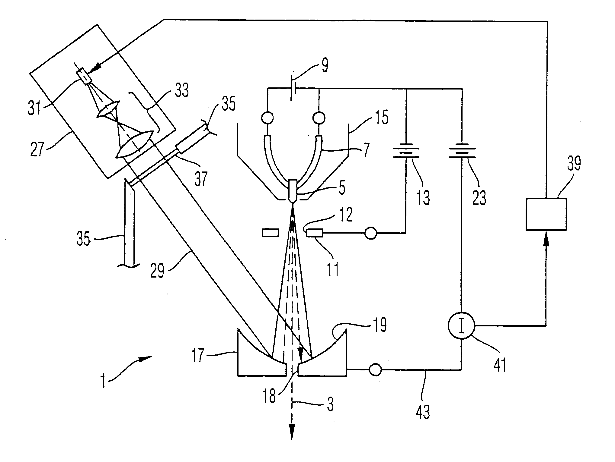
[0038] An electron beam source 1 shown in FIG. 1 is used for generating an electron beam 3 of a predetermined kinetic energy. The electron beam source 1 comprises a thermally heated cathode body 5 mounted on a V-shaped heating wire 7 at a tip of the V-shape. The heating wire 7 is supplied with a heating current provided by a current source 9. The cathode body 5 is of a tip shape at its end oriented in a direction of emission of the electron beam 5. The tip end of the cathode body 5 has a diameter of about 1 .mu.m at its base and provides the source surface of the cathode body 5, i.e. that portion of the surface from which the electrons forming the electron beam 3 emanate.

[0039] The cathode body 5 is made of tungsten and the surface thereof, and in particular the source surface, is covered with a layer of barium oxide such that a work function of the source surface is substantially lower than the work function of tungsten itself. Depending on the method of preparation of the source s...


PUM


Abstract

An electron beam source comprises a source surface illuminated with a photon beam of adjustable intensity. The photon beam assists emission of electrons from the source surface due to a photo effect. An electric extraction field further assists in electron emission. Further, a heater is provided for further assisting in electron emission by a thermionic effect. An electron beam current is measured, and the intensity of the photon beam is adjusted based on the measured electron beam current.

Description

[0001] This application claims priority under 35 U.S.C. .sctn..sctn. 119 and / or 365 to DE 102 45 052.8, filed on Sep. 26, 2002, the entire contens of which is hereby incorporated reference.[0002] 1. Field of the Invention[0003] The invention relates to an electron beam source, a method of operating an electron beam source and an electron optical apparatus using such beam source.[0004] An electron optical apparatus, such as an electron microscope and an electron lithography apparatus using electrons for imaging purposes, comprises at least one electron beam source for providing an electron beam which is used in the apparatus for electron optical imaging or other purposes.[0005] 2. Description of the Related Art[0006] Typical demands which an electron beam source should fulfill are the provision of an electron beam having properties such as a high beam current, a high brightness, an intensity which is sufficiently constant over time, and a low width of a distribution of kinetic energi...

Claims


Application Information

Patent Timeline
Patent Type & Authority Applications(United States)
IPC IPC(8): H01J37/06H01J37/073H01J37/075H01J37/28H01L21/027
CPCH01J37/073H01J37/075H01J2237/065H01J2237/06316H01J37/243
Inventor STEIGERWALD, MICHAEL
Owner CARL ZEISS SMT GMBH
Why Eureka
Try Eureka