Aluminum conductor composite core reinforced cable and method of manufacture

a technology of aluminum conductor and composite core, which is applied in the direction of insulated conductors, cables, power cables, etc., can solve the problems of excessive line sage, and acsr cables suffering from thermal expansion and tensile strength reduction

Inactive Publication Date: 2004-07-08
CTC GLOBAL CORP
View PDF29 Cites 55 Cited by
  • Summary
  • Abstract
  • Description
  • Claims
  • Application Information

AI Technical Summary

Problems solved by technology

Excessive heat will cause the cable to sag below permissible levels.
Above 100.degree. C., ACSR cables suffer from thermal expansion and a reduction in tensile strength.
These physical changes create excessive line sage.
Although ampacity gains can be obtained by increasing the conductor area that surrounds the steel core of the transmission cable, increasing conductor volume increases the weight of the cable and contributes to sag.
Moreover, the increased weight requires the cable to use increased tension in the cable support infrastructure.
Such large weight increases typically would require structural reinforcement or replacement of the electrical transmission towers and utility poles.
Such infrastructure modifications are typically not financially feasible.
The composite core fails in these objectives.
Secondly, a composite core comprising glass fiber and thermoplastic resin does not meet the operating temperatures required for increased ampacity, namely, between 90.degree. C. and 230.degree. C.
Physical properties of composite cores are further limited by processing methods.
Previous processing methods cannot achieve a high fiber to resin ratio by volume or weight.
These processes do not allow for creation of a fiber rich core that will achieve the strength required for electrical cables.
Moreover, the processing speed of previous processing methods is limited by inherent characteristics of the process itself.
The longer dies create increased friction between the composite and the die slowing processing time.
With thousands of miles of cables needed, these slow processing speeds fail to meet the need in a financially acceptable manner.

Method used


Image

  • Aluminum conductor composite core reinforced cable and method of manufacture
  • Aluminum conductor composite core reinforced cable and method of manufacture
  • Aluminum conductor composite core reinforced cable and method of manufacture

Examples


example

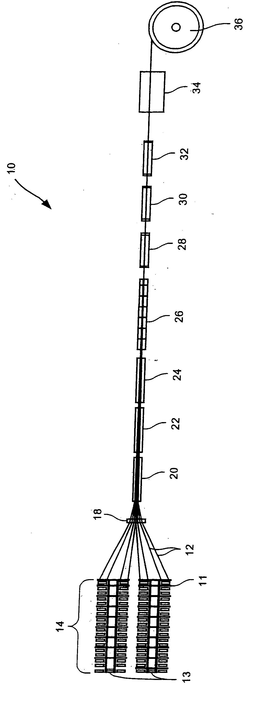
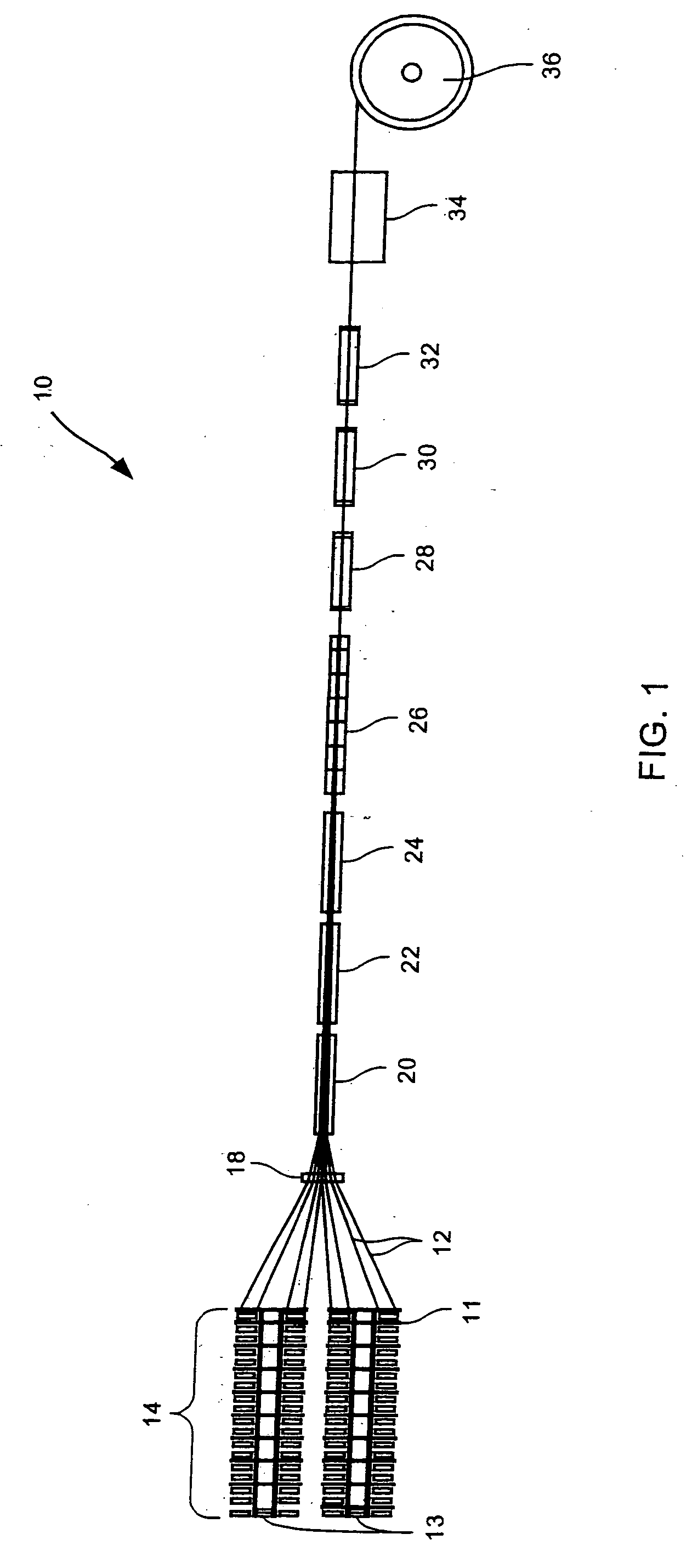
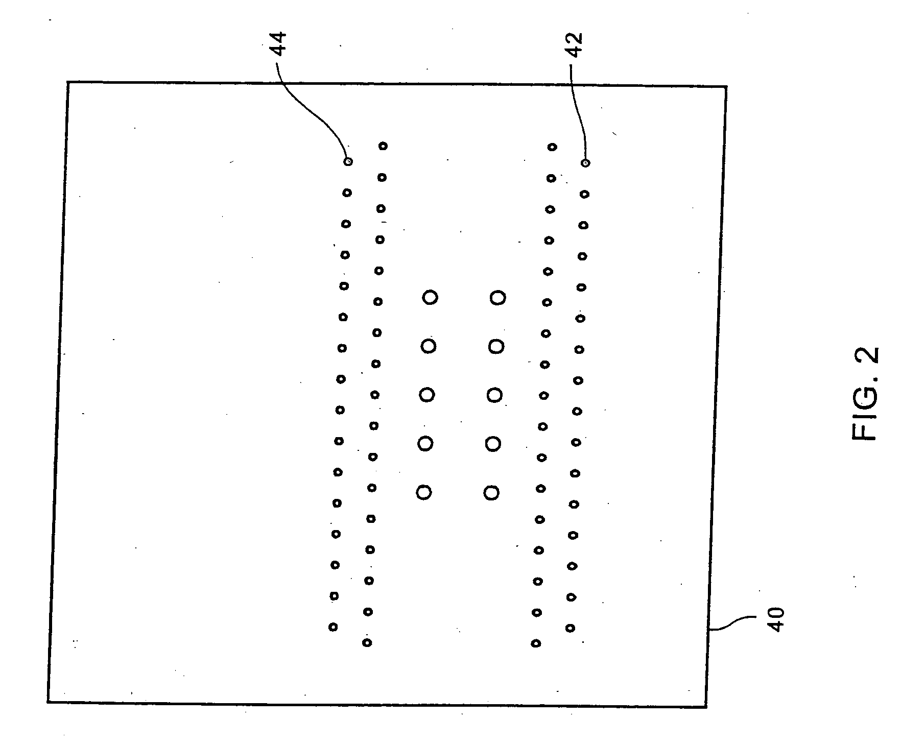
[0153] An example of an ACCC reinforced cable in accordance with the present invention follows. An ACCC reinforced cable comprising four layers of components consisting of an inner carbon fiber and epoxy layer, a next glass fiber and epoxy layer and two layers of tetrahedral shaped aluminum strands. The strength member consists of a high-strength composite T700S carbon fiber and epoxy having a diameter of about 0.2165 inches, surrounded by an outer layer of R099-688 glass fiber and epoxy having a layer diameter of about 0.375 inches. The glass fiber and epoxy layer is surrounded by an inner layer of nine trapezoidal shaped aluminum strands having a diameter of about 0.7415 inches and an outer layer of thirteen trapezoidal shaped aluminum strands having a diameter of about 1.1080 inches. In the cross section, the total area of carbon is about 0.037 in.sup.2, of glass is about 0.074 in.sup.2, of inner aluminum is about 0.315 in.sup.2 and outer aluminum is about 0.5226 in.sup.2. The fi...


PUM

PropertyMeasurementUnit
temperatureaaaaaaaaaa

Abstract

This invention relates to an aluminum conductor composite core reinforced cable (ACCC) and method of manufacture. An ACCC cable has a composite core surrounded by at least one layer of aluminum conductor. The composite core comprises a plurality of fibers from at least one fiber type in one or more matrix materials. The composite core can have a maximum operating temperature capability above 100° C. or within the range of about -45° C. to about 230° C., at least 50% fiber to resin volume fraction, a tensile strength in the range of about 160 Ksi to about 370 Ksi, a modulus of elasticity in the range of about 7 Msi to about 37 Msi and a coefficient of thermal expansion in the range of about -0.7x10<-6 >m/m/° C. to about 6x10<-6 >m/m° C. According to the invention, a B-stage forming process may be used to form the composite core at improved speeds over pultrusion processes wherein the speeds ranges from about 9 ft/min to about 60 ft/min.

Description

[0001] In relation to this Continuation in Part Application, applicants claim priority of earlier PCT filing PCT / US03 / 12520 filed in the International Receiving Office of the United States Patent and Trademark Office on 23 Apr. 2003, the entire disclosure of which is incorporated by reference herein, which claims priority from U.S. provisional application Serial No. 60 / 374,879 filed in the United States Patent and Trademark Office on 23 Apr. 2002, the entire disclosure of which is incorporated by reference herein.[0002] Not ApplicableREFERENCE TO A "MICROFICHE APPENDIX"[0003] Not Applicable[0004] 1. Field of the Invention[0005] The present invention relates to an aluminum conductor composite core (ACCC) reinforced cable and method of manufacture. More particularly, the present invention relates to a cable for providing electrical power having a composite core, formed by fiber reinforcements and a matrix, surrounded by aluminum conductor capable of carrying increased ampacity and ope...

Claims


Application Information

Patent Timeline
Patent Type & Authority Applications(United States)
IPC IPC(8): B32B5/02H01B5/10B32B15/04B32B27/04B32B27/12D02G3/00D04H1/00H01B1/02H01B7/18H01B9/00H01B13/00H02G3/06
CPCB32B15/04B32B27/04H01B5/105H01B7/1825H01B9/006H01B13/0016Y10T428/2933H02G7/056H02G15/06H02G15/18Y10T428/2938Y10T428/2913H02G7/04Y10T442/172Y10T428/24994Y10T428/249945Y10T428/24995Y10T428/249942Y10T428/249949Y10T428/249924Y10T428/249946B32B5/02B29D22/00B32B27/12
Inventor HIEL, CLEMENTKORZENIOWSKI, GEORGE
Owner CTC GLOBAL CORP
Why Eureka
Try Eureka