Method for manufacturing organic electroluminescence panel

a technology of electroluminescence panel and organic material, which is applied in the direction of transportation and packaging, nuclear engineering, railway signalling, etc., can solve the problems of low mechanical strength of organic el element, inability to form protection film, and easy degradation of organic layer by moisture and oxygen

Inactive Publication Date: 2004-07-15
SANYO ELECTRIC CO LTD
View PDF4 Cites 49 Cited by
  • Summary
  • Abstract
  • Description
  • Claims
  • Application Information

AI Technical Summary

Problems solved by technology

Although such organic EL elements have a number of advantages such as achievement of light of various color at a high brightness depending on the organic emissive molecules, the organic EL elements also have disadvantages that the organic layer is easily degraded by moisture and oxygen and that the organic EL element has low mechanical strength.
However, when the protection film is formed using a mask, a method which can achieve high coverage and highly even flatness, such as spin coating, cannot be used to form the protection film.

Method used


Image

  • Method for manufacturing organic electroluminescence panel
  • Method for manufacturing organic electroluminescence panel
  • Method for manufacturing organic electroluminescence panel

Examples


Embodiment Construction

[0026] Preferred embodiments of the present invention (hereinafter simply referred to as "embodiments") will now be described with reference to the drawings.

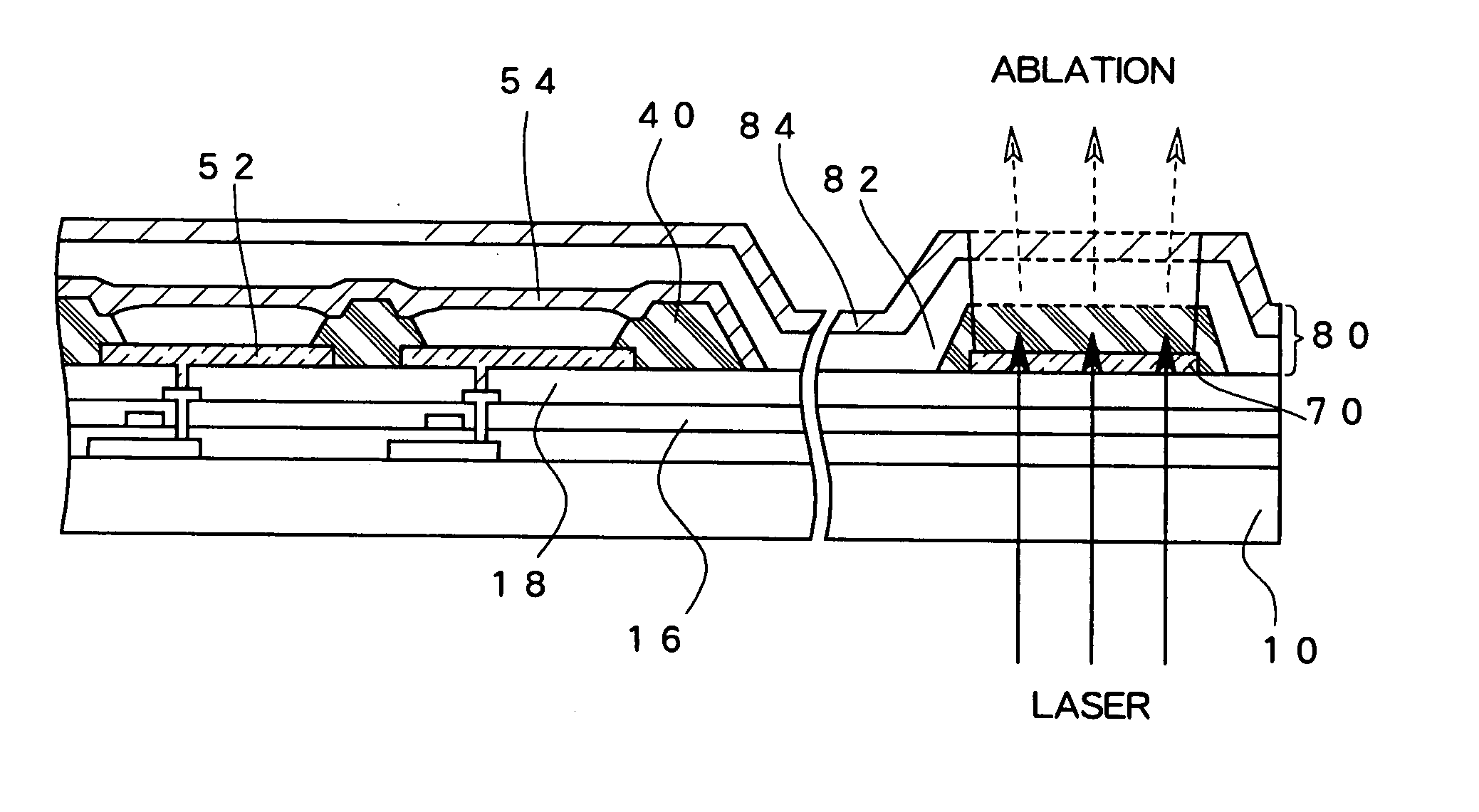
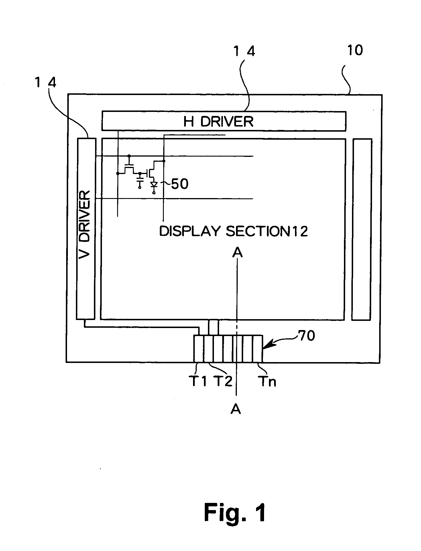
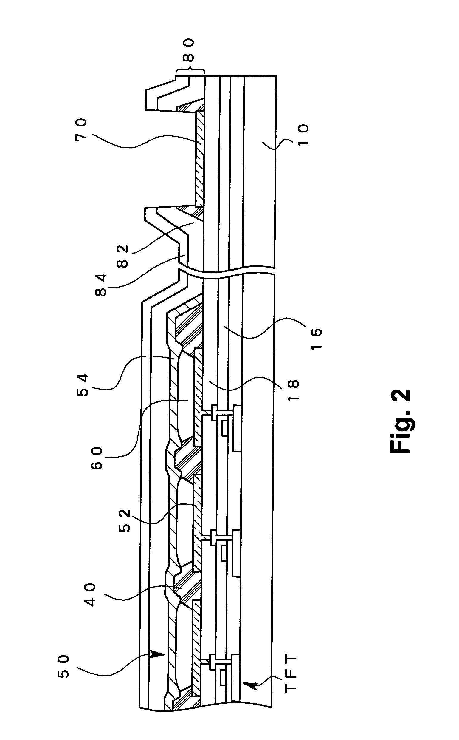
[0027] FIG. 1 is a diagram schematically showing a planar structure of an organic EL panel according to an embodiment of the present invention. FIG. 2 is a cross sectional view along a line A-A in FIG. 1.

[0028] A display section 12 in which a plurality of pixels are provided is formed over a panel substrate 10 made of a material such as glass. An organic EL element 50 is provided in each pixel. The organic EL element 50 has a structure in which an organic layer having emissive molecules is provided between a lower electrode and an upper electrode.

[0029] In this embodiment, the organic EL panel is of an active matrix type, and a switching element (here, a thin film transistor (TFT)) for individually controlling emission of an organic EL element 50 is formed in each pixel. In addition, one of the upper electrode and the lower elec...


PUM


Abstract

A layer of an organic insulating material which functions as a laser removal layer, preferably, a layer of an organic insulating material used during manufacture of an organic EL panel, is formed over a terminal formed when an organic EL element is formed or a TFT for driving the organic EL element is formed. After the organic EL element is formed, a protection film is formed to cover an entire surface of the panel substrate and laser light which can be absorbed by the layer on the terminal covered by the protection film and made of the organic insulating material is irradiated to cause ablation in this layer so that the layer of the organic insulating material and the protection film are simultaneously removed to expose the terminal.

Description

[0001] 1. Field of the Invention[0002] The present invention relates to an organic electroluminescence panel, and, in particular, to a terminal in an organic electroluminescence panel for connection to an external structure.[0003] 2. Description of the Related Art[0004] Because electroluminescence (hereinafter simply referred to as "EL") panels, in which a self-emitting EL element is used as an emissive element in each pixel, have advantages such as that the device is thin, self-emitting, and consumes less power, EL panels have attracted much attention as alternatives to display devices such as liquid crystal display (LCD) and cathode ray tube (CRT) display devices.[0005] An organic EL element has a structure in which an organic layer including organic emissive molecules is provided between an anode and a cathode. Holes injected from the anode and electrons injected from the cathode recombine in the emissive layer to excite the organic emissive molecules, and light is emitted when t...

Claims


Application Information

Patent Timeline
Patent Type & Authority Applications(United States)
IPC IPC(8): B05D3/00B05D5/12H05B33/10H01L27/32H01L51/50H01L51/56H05B33/06H05B33/14
CPCH01L27/3276H01L51/56H01L27/3288H10K59/179H10K59/131H10K71/00H05B33/06
Inventor NISHIKAWA, RYUJI
Owner SANYO ELECTRIC CO LTD
Why Eureka
Try Eureka