Wear surface for metal-on-metal articulation

a technology of wear surface and metal bearing, which is applied in the field of metal on metal bearing prosthetics, can solve the problems of increasing the wear life of the prosthetic joint, affecting the quality of life of the prosthetic, and the difficulty of forming or storing the coating on the prosthetic, so as to reduce the possibility of wear debris and increase longevity

Inactive Publication Date: 2004-07-29
BIOMET MFG CORP
View PDF31 Cites 34 Cited by
  • Summary
  • Abstract
  • Description
  • Claims
  • Application Information

AI Technical Summary

Benefits of technology

0007] A metal on metal bearing prosthetic having articulating surfaces formed of metal. No additional bearing component is included between the articulating portions of the prosthetic. The articulating surfaces of the bearing prosthetic are hardened to increase longevity and decrease possible wear debris during articulation of the prosthetic. The articulating or bearing surfaces of the prosthetic are generally hardened to at least...

Problems solved by technology

This generally increases the wear life of the prosthetic joint.
Nevertheless, the MOM prosthetics may encounter greater wear because two hardened surfaces continually articulate against one another.
Forming or depositing the coating on the prosth...

Method used


Image

  • Wear surface for metal-on-metal articulation
  • Wear surface for metal-on-metal articulation
  • Wear surface for metal-on-metal articulation

Examples


example 1

Hardening the Stock Material

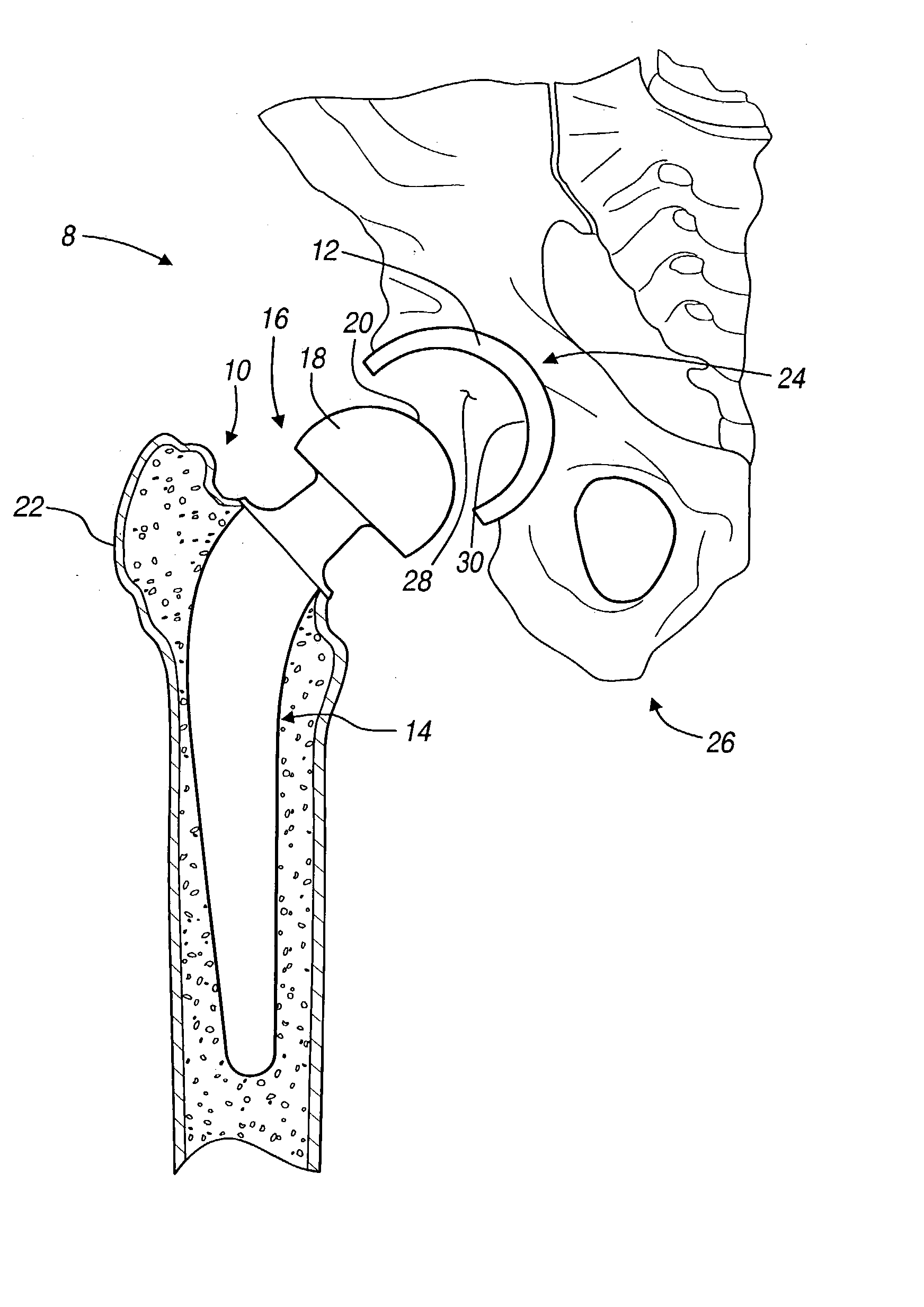
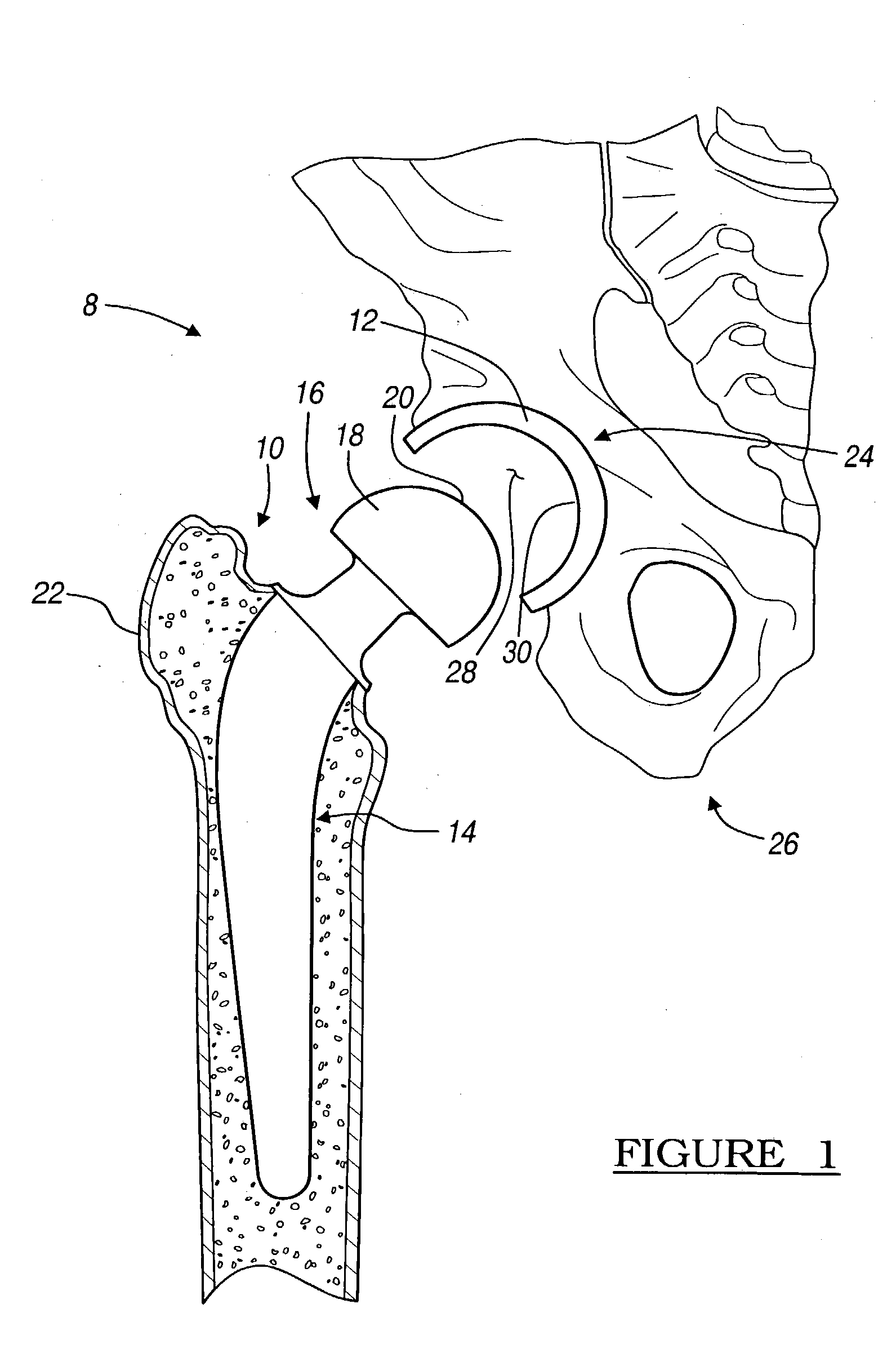
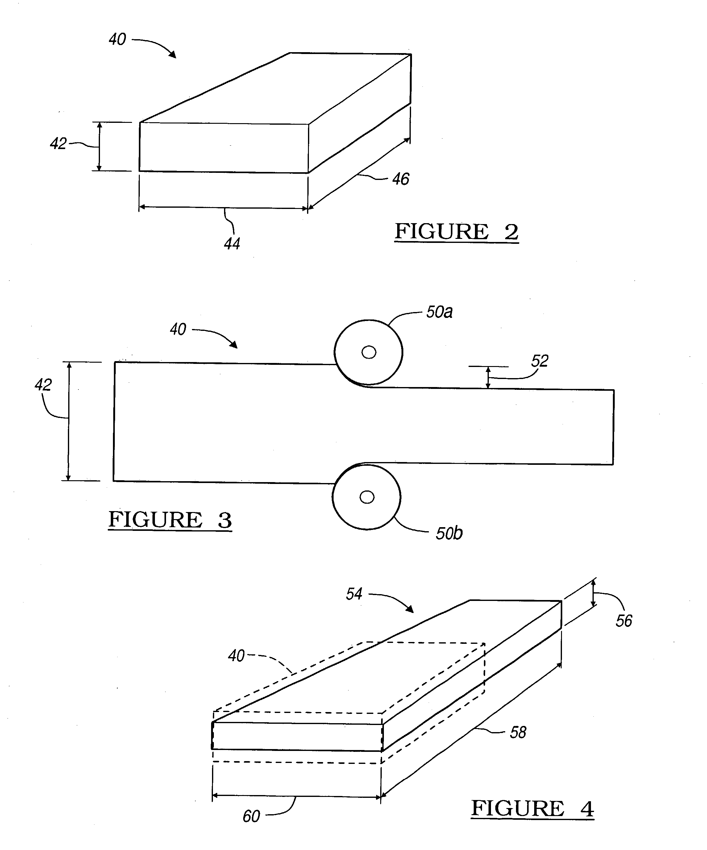
[0028] With reference to FIG. 2, prosthetics, such as the hip prosthetic 8, are generally formed from a stock bar member 40. The stock member 40 may be any appropriate bio-compatible material but generally includes an alloy of cobalt, chromium, and molybdenum (CoCrMo). The unhardened stock member 40 generally includes a first set of unhardened dimensions. Generally, the dimensions include an unhardened height 42, width 44, and depth 46. Work hardening can then be performed on the non-work hardened stock member 40 through any generally known hardening methods. For example, the material may be shot peened, roller hardened, or laser shocked to induce the desired hardness. Generally, however, to induce enough hardness throughout the entire stock member 40, an intense physical working such as roller working is used.

[0029] When performing roller hardening, any one of the three unwork hardened dimensions 42, 44, 46 may be reduced. With reference to FIG. 3, the s...

example 2

Hardening a Rough Formed Prosthetic

[0033] With reference to FIG. 5, a detailed portion of an unfinished or rough worked head member 60 is illustrated. The unfinished head member 60 includes a final or finished selected surface dimension 62 and an unfinished surface dimension 64. Generally, the unfinished surface dimension 64 is greater than the finished dimension 62. Therefore, the unfinished head member 60 must be finished in some method to reduce the unfinished dimension 64 to the finished selected dimension 62.

[0034] When the unfinished head member 60 is formed from a non-work hardened stock member, such as the non-work hardened stock member 40, the unfinished head member 60 can be work hardened by generally known methods. For example, the unfinished head member 60 can be hardened with shot peening or laser shot peening to increase the hardness of the surface.

[0035] With reference to FIG. 6, once the rough formed head 60 has been hardened, such as through shot peening, the shot p...


PUM

PropertyMeasurementUnit
Lengthaaaaaaaaaa
Hardnessaaaaaaaaaa

Abstract

A work hardened articulating surface for anatomical prosthetics. Articulating surfaces of prosthetics are work hardened to decrease the wear and increase the longevity of the prosthetic after implantation. The articulating surface can be hardened in any number of ways, for example the articulating surface can be formed from stock material that has been work hardened throughout or the articulating surface can be work hardened prior to final finishing of the prosthetic component. Regardless, the hardened articulating surface reduces wear after implantation while eliminating the need for a separate bearing component.

Description

[0001] The disclosure relates to bearing or articulating components in prosthetics, and particularly relates to metal on metal bearing surfaces for use in a prosthetic.[0002] Modern medical interventions enable many portions of the anatomy to be replaced by prosthetic devices, including load bearing or articulating joints. Exemplary bearing joints include the ball and socket of the hip joint and the shoulder joint. Although these are exemplary bearing joints, many other joints, which also have articulating surface, may also be replaced such as the flanges or knee joints.[0003] Often, the bearing joints are replaced with allograft or xenograft prosthetic materials that are at least as hard as the natural bone. A bearing is often placed between the harder portions in a bearing prosthetic. The bearing can include an ultra-high molecular weight polyethylene (UHMWPE) bearing surface. The UHMWPE provides a substantially smooth and cushioned bearing surface between the hard articulation su...

Claims


Application Information

Patent Timeline
IPC IPC(8): A61F2/00A61F2/28A61F2/30A61F2/32A61F2/34A61F2/36A61F2/38B24C1/10
CPCA61F2/30767B24C1/10A61F2/32A61F2/34A61F2/36A61F2/3662A61F2/38A61F2/3859A61F2/389A61F2002/30685A61F2002/30878A61F2002/30922A61F2002/30924A61F2002/30934A61F2002/3446A61F2002/3611A61F2002/3625A61F2002/3631A61F2002/365A61F2310/00029A61F2/3094
Inventor SCHROEDER, DAVID WAYNE
Owner BIOMET MFG CORP
Why Eureka
Try Eureka