Method of receiving and transmitting the signal of high frequency

a high-frequency signal and processing method technology, applied in the field of processing of rf frequency signals for receiving and transmission, can solve the problems of inability to make filter components such as filters and duplexers, which cannot be made using normal inductors and capacitors, and are sensitive to manufacturing and assembly tolerances, so as to facilitate the integration of the whole transmitter into ics, reduce the requirement for filtering components 16, and facilitate the effect of implementing

Inactive Publication Date: 2004-08-05
UNIVERSITY OF SURREY
View PDF16 Cites 1 Cited by
  • Summary
  • Abstract
  • Description
  • Claims
  • Application Information

AI Technical Summary

Benefits of technology

[0010] It is noted particularly that in this invention, the processing of the desired signal by Mixer 4 and Mixer 7 form a spread--de-spread process. As to the image interference, there are two scenarios: the first, f5, the frequency of the 1.sup.st LO signal, is varied between the frequency of the desired received signal, noted as fs, and the frequency of the image interference, noted as fi, at Point B, the image interference is spread in Mixer 4 and is spread again in Mixer 7 (spread-spread); the second, if f5 is varied outside of the frequency range between fs and fi at Point B, then the image interference is spread by Mixer 4 whose fi at Point D will have the same distance with fs as at Point B. It is thus easier to filter the image interference out at the IF Filter 6 then if it were done at the RF section between Points A and B, since while having the same distance between fi and fs, the distance / fs ratio can be set to be much larger at IF Point D than at RF Point B. So in both scenarios, image interference can be effectively attenuated by the receive in this invention.
[0032] (12) Due to the spreading of various spurious signals, which leads to relaxed filtering requirements for the filtering component 16, the insertion loss of 16 can be reduced, which effectively increases the gain and the power consumption efficiency of the transmitter.

Problems solved by technology

In either of the receiving and transmitting processes, due to the strict signal filtering requirements, filtering components, such as filters and duplexers, usually cannot be made using normal inductors and capacitors, especially those which can be integrated into semiconductor ICs.
While these components works well, they are bulky in size, expensive, sensitive to manufacturing and assembly tolerances and are difficult to be integrated into ICs, which forms one of the major obstacles to integrate a circuit system into a single chip.
However, its application has been limited to certain types of systems, due to issues such as DC offset, sensitivities, etc., which lower the performance of the receivers and require demanding compensation and processes.

Method used


Image

  • Method of receiving and transmitting the signal of high frequency
  • Method of receiving and transmitting the signal of high frequency

Examples


Embodiment Construction

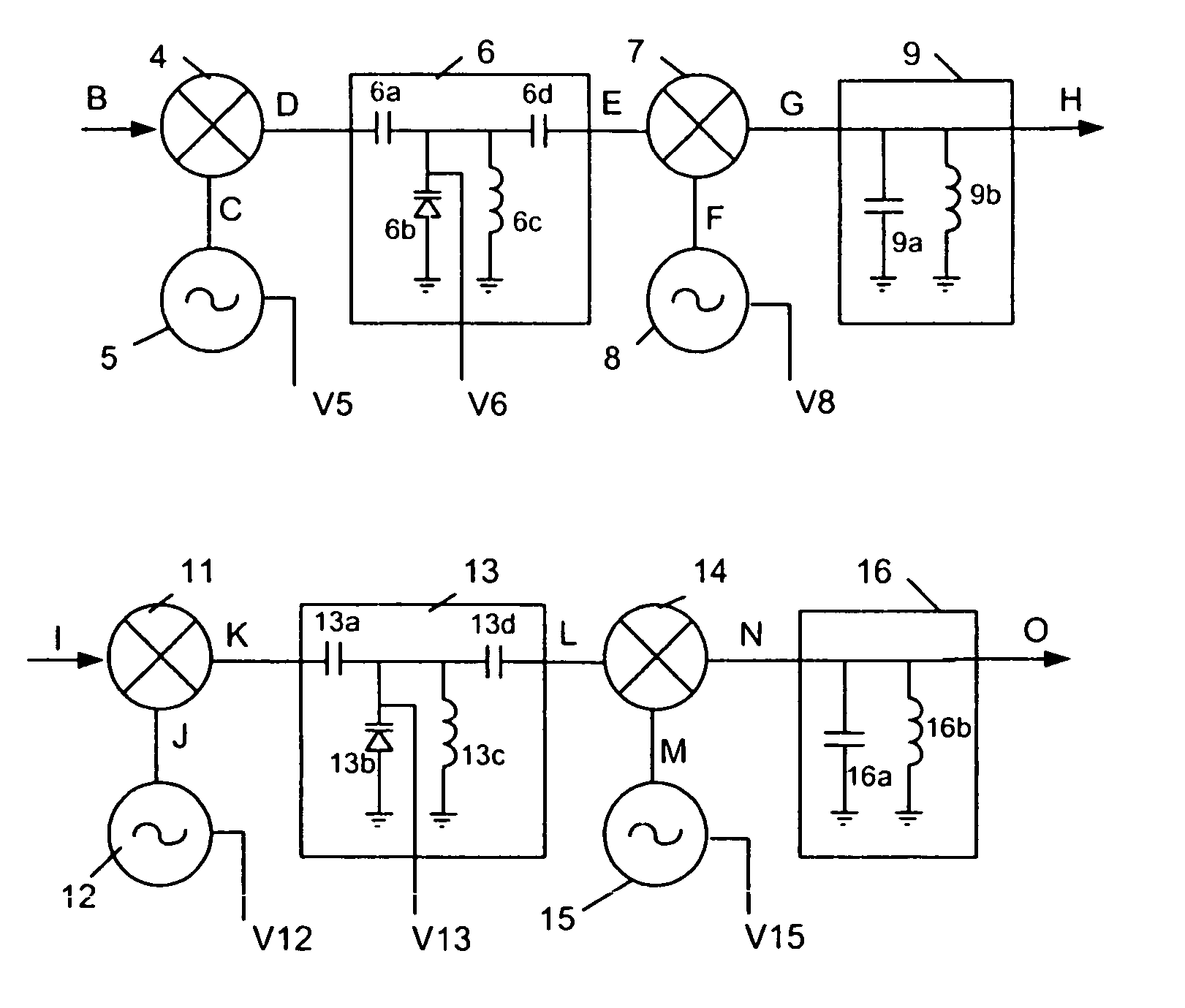
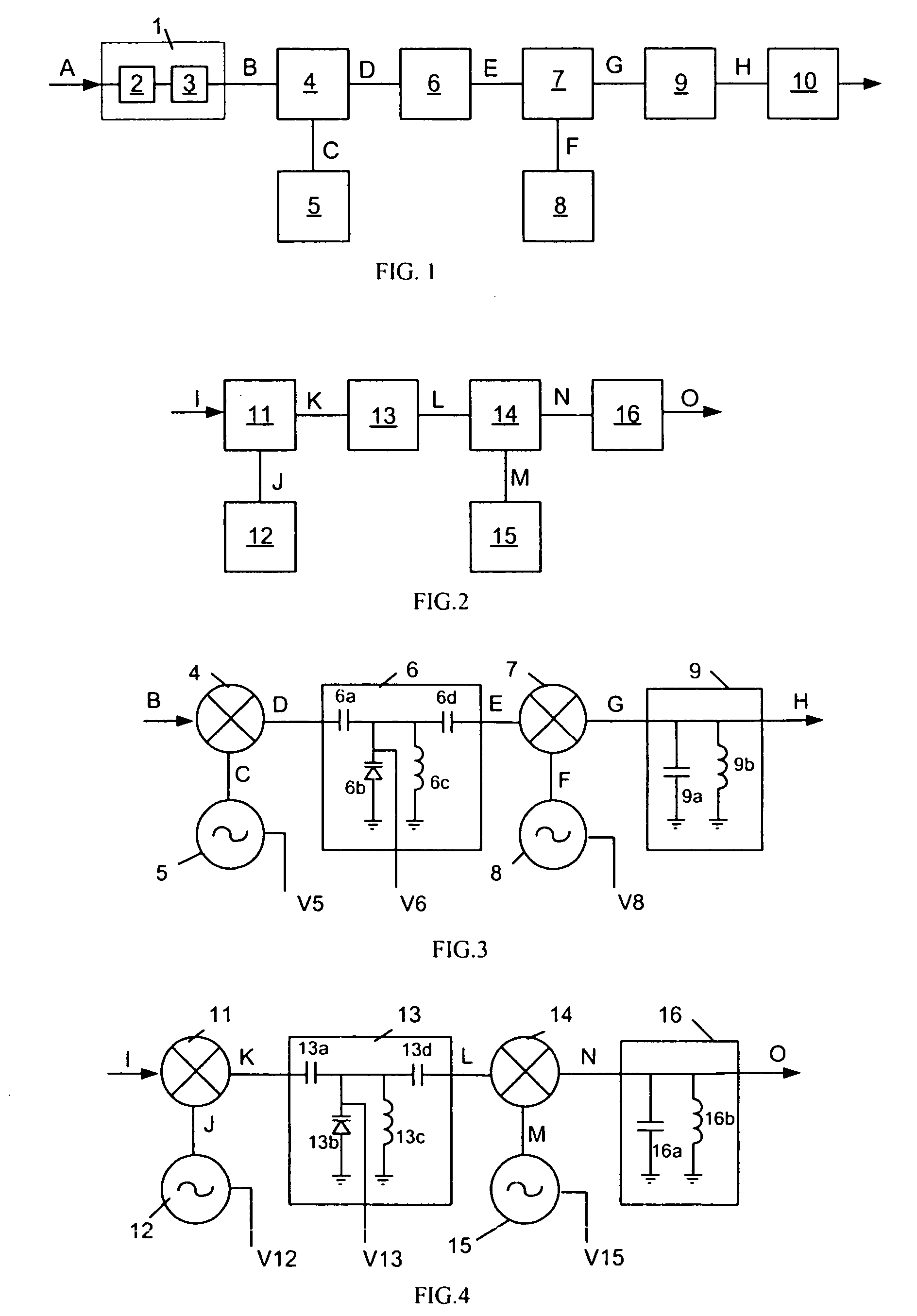
[0037] Refer to FIG. 3, it shows a circuit implementation of the core functional blocks from Point B to Point H of the receiver in FIG. 1 in the invention. It can be seen from FIG. 3 that the interconnections of the functional blocks, namely, 1.sup.st Mixer 4, 1.sup.st LO Source 5, 1.sup.st IF Filter 6, 2.sup.nd Mixer 7, 2.sup.nd LO Source 8 and 2.sup.nd IF Filter 9, are the same as those in FIG. 1. A circuit implementation for each of the above blocks is described as follows: Frequency conversions are performed with Mixers 4 and 7. Voltage-controlled Oscillators are used as the 1.sup.st and 2.sup.nd LO sources 5 and 8, whose output frequencies vary as functions of voltages V5 and V8, respectively. The 1.sup.st IF Filter 6 is a band pass filter. Its input is at Point D connected to Capacitor 6a. The other terminal of Capacitor 6a is connected to the cathode of Varactor 6b, Inductor 6c and Capacitor 6d. The anode of Varactor 6b and the other terminal of Inductor 6c are grounded. The ...


PUM


Abstract

Methodology for processing of RF signals for receiving and transmission, which varies the frequencies of local oscillators, in order to enable the receivers and transmitters to operate with higher performance in wider or multi-bands. Their integrations into ICs are also made easier.

Description

FIELD[0001] The present invention relates to a methodology for the processing of RF frequency signals for receiving and transmission, and particularly to such an technique to suppress effectively (a) image and other interference signals in receiving and (b) interference to the channel and the receiving sides of the circuit when transmitting, without using high quality filtering components at RF frequencies which are difficult to integrate into ICs.[0002] In communication fields, RF frequencies are often used as carriers for signal receiving and transmission. Typically using current techniques, in the receiver, modulated RF frequency signals are received, filtered to attenuate interference- especially image-signals, before being down converted to IF frequencies. In the transmitter, filtering is also needed before the signals are transmitted, in order to reduce their interferences to communication channels and the receiving side of the circuits. In either of the receiving and transmit...

Claims


Application Information

Patent Timeline
Patent Type & Authority Applications(United States)
IPC IPC(8): H04B1/28
CPCH04B1/28
Inventor XUAN, YONGNANFENG, SUILI
Owner UNIVERSITY OF SURREY
Why Eureka
Try Eureka