
Method of optically measuring black carbon in the atmosphere and apparatus for carrying out the method

a black carbon and atmosphere technology, applied in the direction of measurement devices, instruments, material analysis, etc., can solve the problems of unsuitable air intake for larger particle diameters, serious falsification of measured values, and failure to make it possible to furnish measuring data

Active Publication Date: 2004-08-12
DEUTSCHES ZENTRUM FUER LUFT & RAUMFAHRT EV +1
View PDF8 Cites 10 Cited by
  • Summary
  • Abstract
  • Description
  • Claims
  • Application Information

AI Technical Summary

Benefits of technology

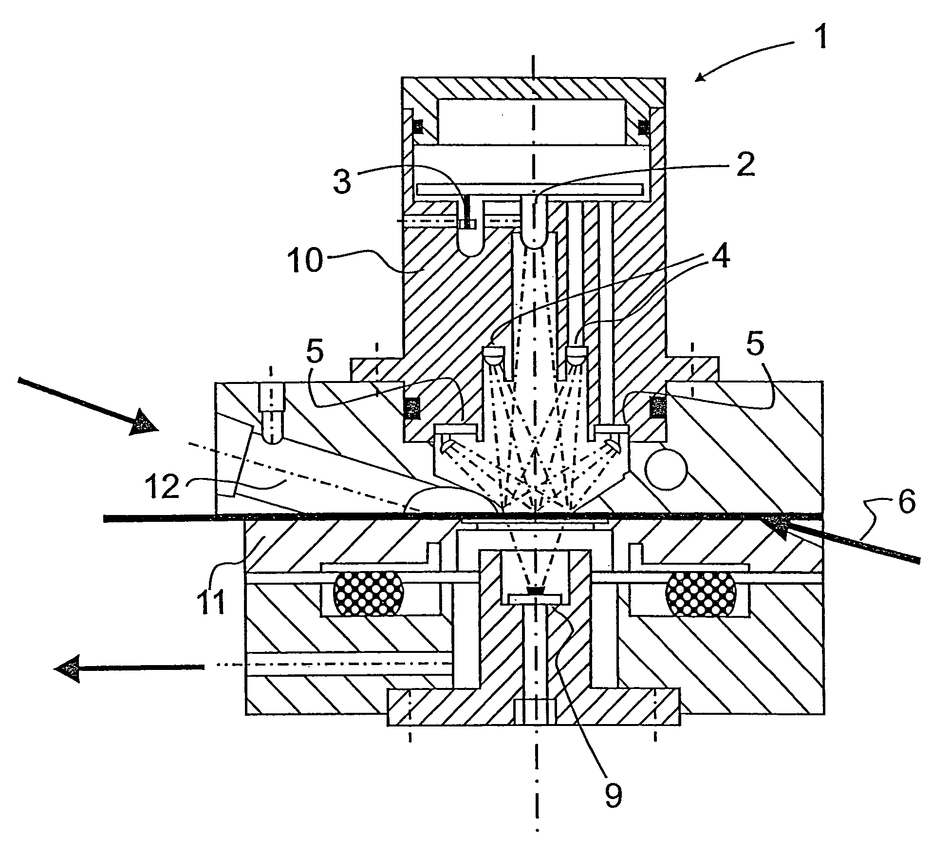
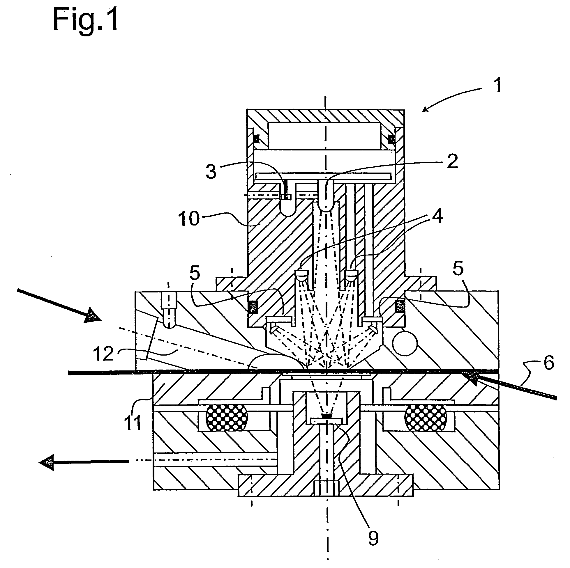
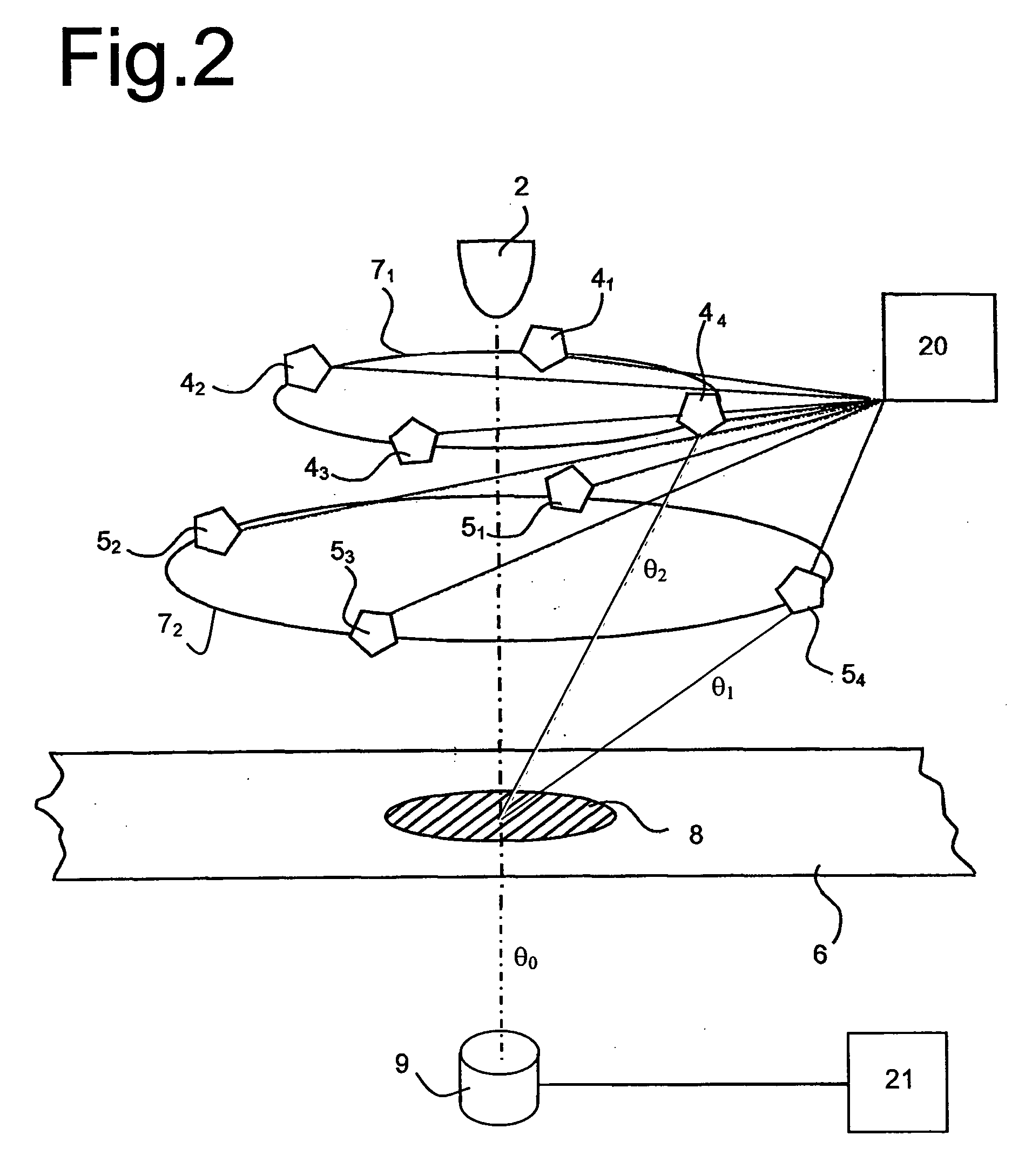
[0011] In accordance with the invention for measuring the transmitted and reflected light fractions the photodetectors are arranged opposite each other at precisely defined angles or angle ranges of 0.degree., 120.degree. to 140.degree. and from 165.degree. to 180.degree. preferably in ring-shaped mounting devices arranged concentrically to the optical axis of the at least one illumination source. The resulting maximum symmetry in the multiple angle measurement assembly in accordance with the invention for the angle ranges to be measured enhances a signal average over an expansive filter area for a highly compact structure of a measuring apparatus in the form of a measuring head.
[0012] To reduce scattered light the ring-shaped mounting devices in which the photodetectors are mounted opposite each other are preferably defined in two different planes.

Problems solved by technology

This, however, fails to make it possible to furnish the measuring data resolved in time / on a daily basis.
This cross-sensitivity may result in the measured values being seriously falsified.
Apart from this, the air intake is unsuitable for larger particle diameters.

Method used


Image

  • Method of optically measuring black carbon in the atmosphere and apparatus for carrying out the method
  • Method of optically measuring black carbon in the atmosphere and apparatus for carrying out the method
  • Method of optically measuring black carbon in the atmosphere and apparatus for carrying out the method

Examples


Embodiment Construction

[0041] The described method was put to use in determining the black carbon content in a mixture of light-scattering carbon). The mass percentage of the black carbon varied between 1% and 100%. In an ideal method the change in the optical filter properties (transmissivity, equation (1a), reflectivity, equation (1b), absorptance, equation (5)) caused by the particle loading of the filter is directly proportional to the loading of the filter with black carbon and is thus represented by an originating straight line.

[0042] FIG. 6 shows the relationship between the measured values ATN, REF and ABS and the loading of the filter with black carbon as measured independently in accordance with VDI 2465, Sheet 1, i.e. for a transmission measurement (ATN), reflectivity measurement (REF) and for the method as described (ABS).

[0043] Table 1 lists the corresponding results of the correlation analysis. The multiple angle absorption measurement as described above thus exhibits high correlation for si...


PUM

PropertyMeasurementUnit
angles/angleaaaaaaaaaa

Abstract

For optically measuring black carbon in the atmosphere an aerosol particle collection area of a filter tape is continually illuminated by an illumination source with light of one or more wavelengths. Transmitted and reflected light fractions are measured at several precisely defined angles or angle ranges, such as of 0°, 12° to 140° and 165 to 180° by means of photodetectors arranged correspondingly relative to the illumination source, achieving maximum symmetry for the angles to be measured. The loading of the filter tape collection area with light absorbing aerosol material is continually determined from the change in the optical properties of the collection area with the aid of known algorithms from transmissivities and reflectivities as detected.

Description

[0001] The invention relates to a method of optically measuring black carbon in the atmosphere and an apparatus for carrying out the method.PRIOR ART[0002] Black carbon (soot) is a leading component in particulate emissions from an incomplete combustion process. The German Standard hitherto for measuring black carbon in the air is VDI 2465 Sheet 1 / 2. The guideline requirements define thermal methods as a reference for immission measurements of black carbon, with the aid of which daily or weekly filter data is analyzed. This, however, fails to make it possible to furnish the measuring data resolved in time / on a daily basis.[0003] For optically measuring black carbon the ambient aerosol is deposited on a single filter or filter tape. The change in the optical properties of the particle-loaded filter matrix as compared to a particle-free matrix is determined either in transmission (ATN) or in reflexion (REF). The change in the blackening of the filter due to particle loading is an indi...

Claims


Application Information

Patent Timeline
Patent Type & Authority Applications(United States)
IPC IPC(8): G01N21/47G01N21/49G01N21/53G01N21/59
CPCG01N21/47G01N21/59G01N21/532
Inventor PETZOLD, ANDREASSCHONLINNER, MARKUS
Owner DEUTSCHES ZENTRUM FUER LUFT & RAUMFAHRT EV
Learn More