Eureka AIR delivers breakthrough ideas for toughest innovation challenges, trusted by R&D personnel around the world.

Electrochemical cell

a technology of electrochemical cells and cell membranes, applied in the field of electrochemical cells, can solve the problems of increasing the cost in view of increasing the number of parts and manufacturing steps, increasing the cost, and reducing the size of the sealing space, and unable to achieve sealing at a high reliability

Inactive Publication Date: 2004-08-12
WATANABE SHUNJI +3
View PDF8 Cites 44 Cited by
  • Summary
  • Abstract
  • Description
  • Claims
  • Application Information

AI Technical Summary

Problems solved by technology

In the existent electrochemical cell, since the cross section has a circular shape such as coin or a button it is necessary that terminals, etc. have to be welded previously to the casing for conducting reflow soldering, which increased the cost in view of increase in the number of parts and increase in the number of manufacturing steps.
While an electrochemical cell of a square shape has also been studied, it has become difficult to take a sealing space along with reduction of the size.
However, since the non-aqueous electrolyte cell or electric double layer capacitor contains an electrolyte in the inside, it was impossible to attain sealing at a high reliability unless a margin is provided for the bonded portion to some extent.

Method used


Image

  • Electrochemical cell
  • Electrochemical cell
  • Electrochemical cell

Examples


Embodiment Construction

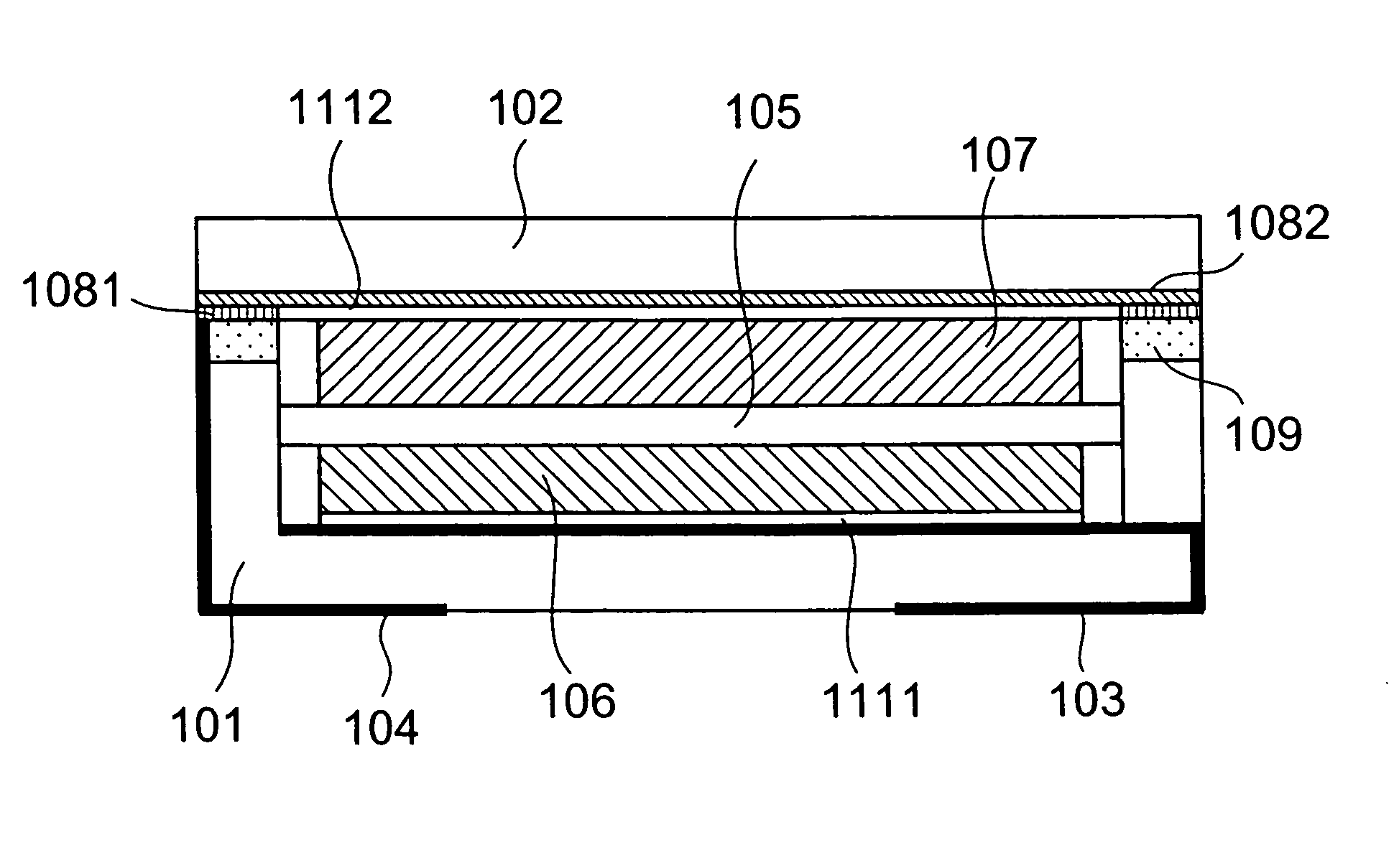
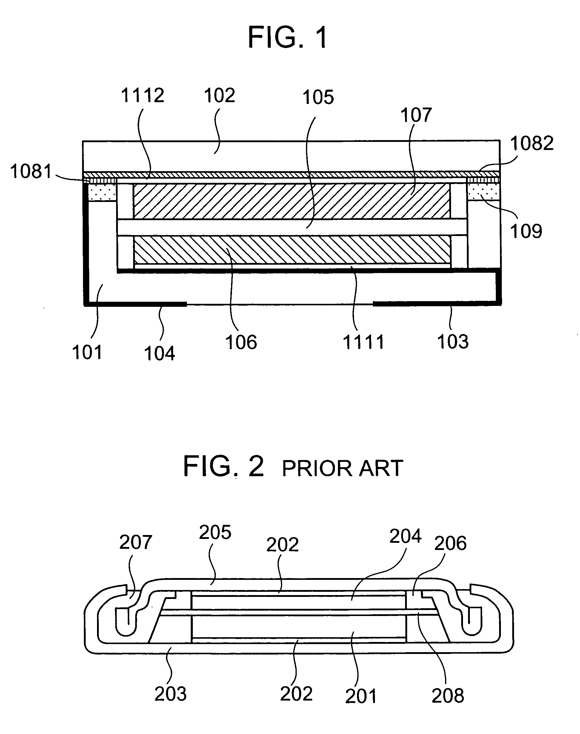
[0025] The present invention is to be described for a typical structure with reference to FIG. 1. In the non-aqueous electrolyte cell or electric double layer capacitor of the invention, it is effective to make the shape, mainly, as a rectangular pyramidal form for reducing the ratio of mounting are to the space in surface mounting.

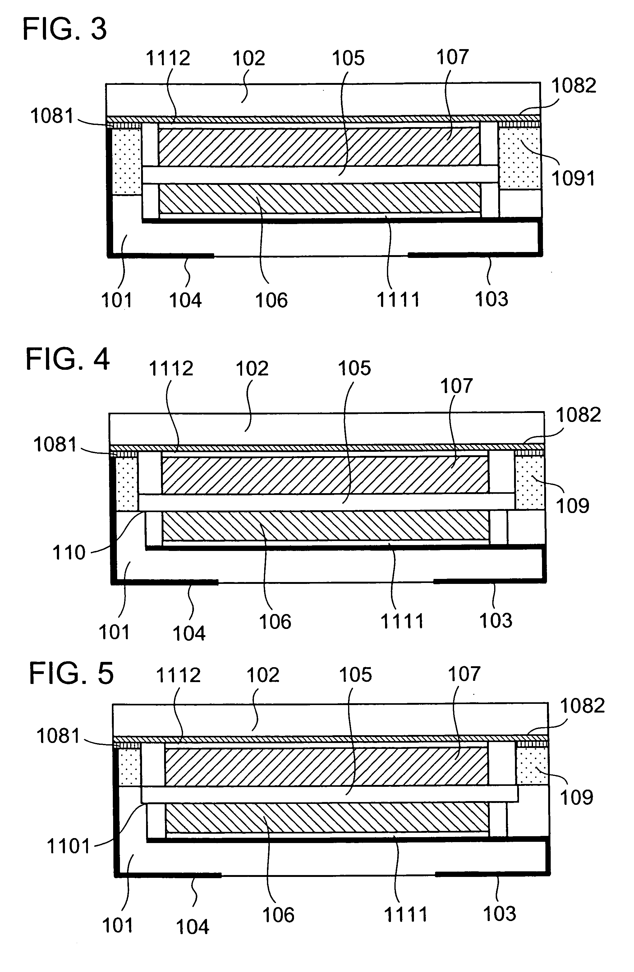
[0026] FIG. 1 is a cross sectional view of a non-aqueous electrolyte cell or electric double layer capacitor of the invention in the rectangular pyramidal form. A concave vessel 101 is made of alumina prepared by printing tungsten on a green sheet, placing a metal ring 109 made of Coval (alloy comprising Co: 17, Ni: 29, Fe: balance) thereon and sintering them. Further, a connection terminal A 103 and a connection terminal B 104 are applied with nickel / gold plating, and nickel and gold plating was applied as a brazing material 1081 (brazing material) on the metal ring 109. It was manufactured by the same method as a ceramic package for a usual quartz oscil...


PUM

PropertyMeasurementUnit
melting pointaaaaaaaaaa

Abstract

For avoiding problems in existent non-aqueous electrolyte cells or electric double layer capacitors of a rectangular pyramidal shape that sealing at high reliability can not be attained unless a bonded portion has a margin of a certain degree in view of electrolytes contained therein, a metal layer comprising a metal ring and a brazing material having a heat expansion coefficient approximate to that of a concave vessel of a non-aqueous electrolyte cell or an electric doceble layer capacitor is disposed to the edge of the vessel, a sealing plate made of a metal having a property similar with the metal ring and having a brazing material layer at the bonded surface is also used for the sealing plate and, further, paired electrodes comprising a positive electrode and a negative electrode, a separator and an electrolyte are contained in the concave vessel, the sealing plate is placed on the vessel and seam welding is conducted by using a resistance welding method thereby capable of attaining sealing at high reliability.

Description

[0001] 1. Field of the Invention[0002] The present invention concerns an electrochemical cell capable of being surface-mounted such as a non-aqueous electrolyte cell and an electric double layer capacitor utilizing the principle of the electric double layer.[0003] 2. Statement of the Prior Art[0004] Electrochemical cells such as non-aqueous electrolyte cells and electric double layer capacitors have been used so far as back-up power sources for clock function, back-up power sources for semiconductor memories, spare power sources for electronic devices such as microcomputers or IC memories, cells for solar clocks and motor driving power sources and, in recent years, they have also been studied, for example, as power sources for electric motor cars and auxiliary power storage units for energy conversion storage systems.[0005] In electrochemical cells such as non-aqueous electrolyte cells and electric double layer capacitors, requirement for large capacity and current has been decrease...

Claims


Application Information

Patent Timeline
Patent Type & Authority Applications(United States)
IPC IPC(8): H01G9/02H01G11/00H01G11/28H01G11/52H01G11/58H01G11/66H01G11/68H01G11/70H01G11/74H01G11/78H01G11/82H01G11/84H01G11/86H01M4/64H01M4/66H01M10/05H01M10/058H01M50/414
CPCH01M2/0426H01M2/1633H01M2/162Y02E60/10H01M50/169H01M50/446H01M50/44Y02P70/50H01M50/414
Inventor WATANABE, SHUNJINAKAMURA, YOSHIBUMIONODERA, HIDEHARUSAKAI, TSUGIO
Owner WATANABE SHUNJI
Why Eureka
Eureka Blog
Learn More