Drill bit cutter element having multiple cusps

a cutter element and cutter element technology, applied in cutting machines, earth drilling and mining, construction, etc., can solve the problems of increasing the tensile stress of the cutter element, increasing the tensile stress of the region around the crater made by the cutter element, and reducing the tensile stress of the cutter element, so as to improve the tensile stress and enhance the formation material. , the effect of increasing the rop of the bi

Inactive Publication Date: 2004-08-26
SMITH INT INC
View PDF20 Cites 44 Cited by
  • Summary
  • Abstract
  • Description
  • Claims
  • Application Information

AI Technical Summary

Benefits of technology

0021] Described herein is an enhanced cutter element for use in a rolling cone drill bit particularly suited for enhancing brittle rock formation and increasing ROP of a bit. The cutter element includes a base portion and a cutting portion extending from the base, the cutting portion including a crown on the cutting surface having a plurality of spaced-apart cusps with valleys between the cusps. The cusps may be partial dome-shaped cusps of the same or differing radius of curvature. Further, the cusps may extend the same distance from the base or, alternatively, the cusps may differ in extension. In certain embodiments, it is desirable to provide a cutting portion that extends beyond the outer profile of the base. The spaced-apart cusps impact the formation material and create a relatively large Hertzian contact zone to enhance formation material relative to a conventional conical insert of similar diameter and extension.
0022] The cutter elements described herein may be placed in various rows in the cone cutter; however, certain cutter elements include features that provide greater enhancements when used in particular rows. For example, cutter elements described herein having relatively short extensions may, in many cases, be better suited for use in the heel row for scraping the side wall of the borehole. In addition to partial dome-shaped cusps, the cutter elements may include a plurality of berm-shaped cusps circumferentially disposed about the cutting surface crown with valleys separating the berms so as to create a crenellated crown. Central to the circumferentially disposed berms may be a central recess or a central cusp that is separated from the surrounding berms by a cicunferential valley. The cutting surface provided by such structure provides a myriad of cutting edges. The upper surface of the berm like cusps may themselves include projections or apexes that are separated by a saddle. Such a cutter element offers still further cutting edges to the formation material.

Problems solved by technology

As is thus obvious, this process, known as a "trip" of the drill string, requires considerable time, effort and expense.
That is, when the rock first undergoes plastic fracture, a region around the crater made by the cutter element will experience increased tensile stress and will weaken and may crack in that region, even though the rock in that region surrounding the crater has not been displaced.
However, in certain formations, when the cutter element displaces enough of the rock and creates enough stress in the Hertzian contact zone adjacent to the plastic fracture, that rock in the region of increased stress may itself break and chip away from the crater.
Unfortunately, however, conventional cutter elements, such as a chisel shaped insert, having a single primary cutting edge, are usually oriented to optimize the cutting that takes place only in the cutter's circumferential cutting trajectory, as they do not have particular features to take advantage of cutting opportunities as the cutter element twists.

Method used


Image

  • Drill bit cutter element having multiple cusps
  • Drill bit cutter element having multiple cusps
  • Drill bit cutter element having multiple cusps

Examples


Embodiment Construction

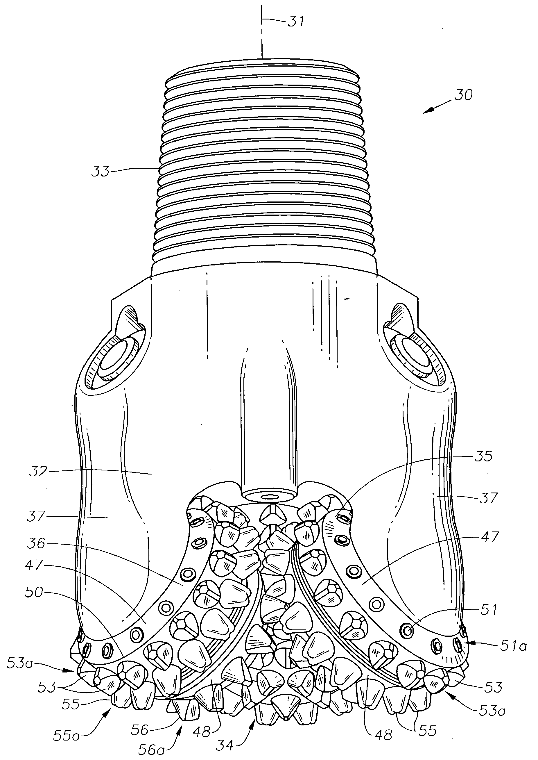
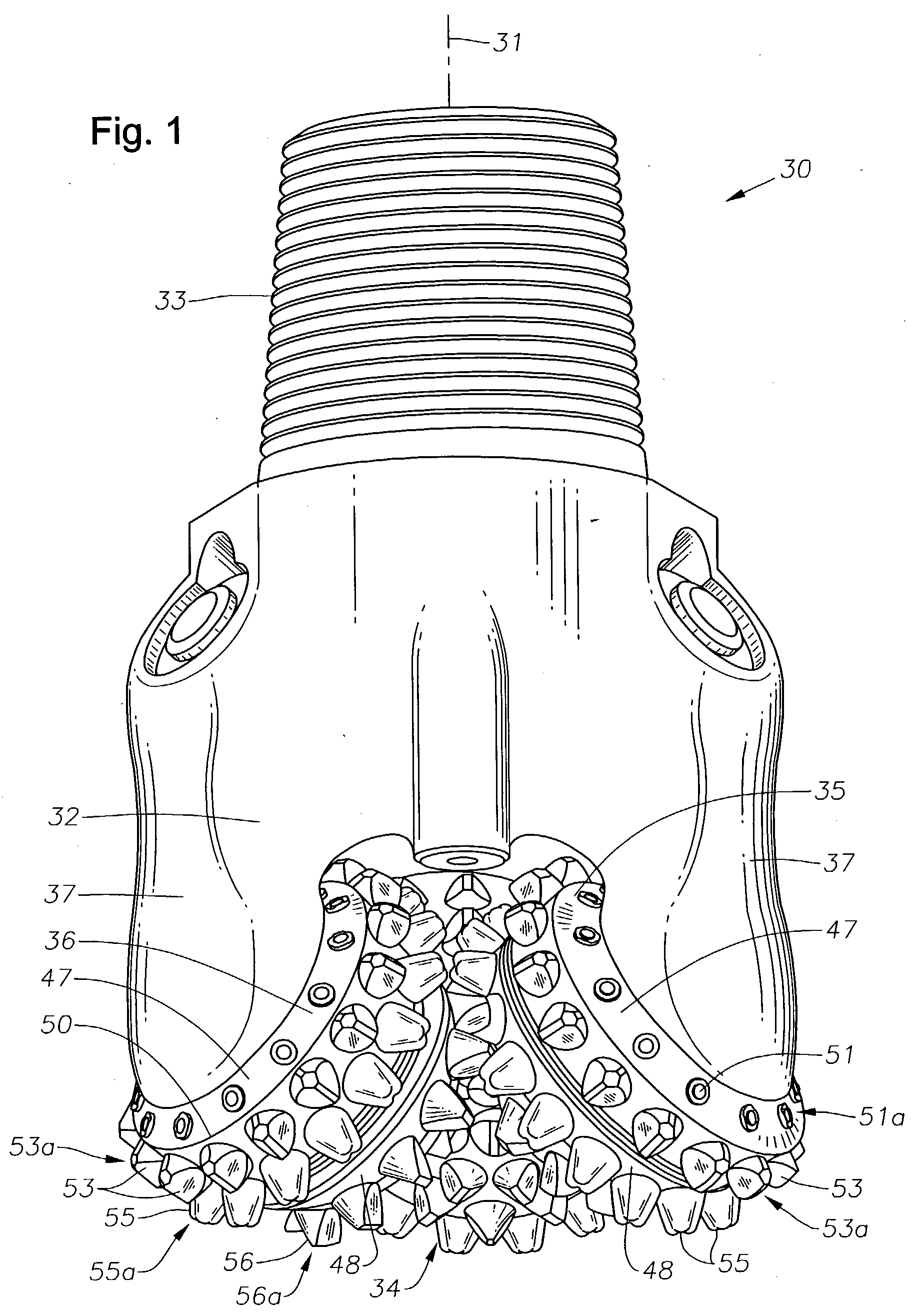
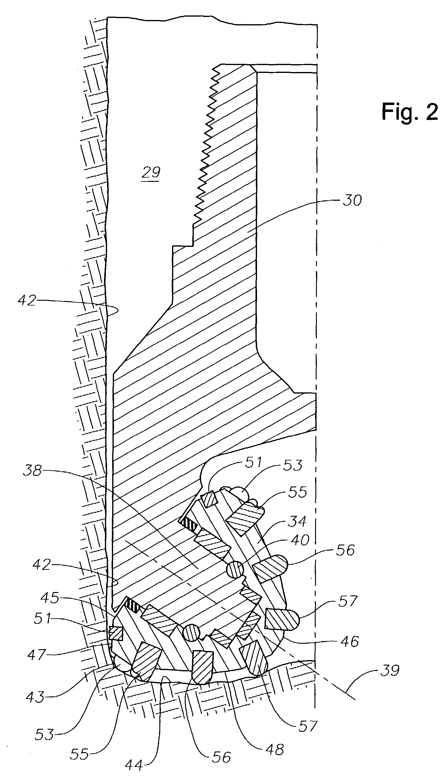
[0021] Described herein is an enhanced cutter element for use in a rolling cone drill bit particularly suited for enhancing brittle rock formation and increasing ROP of a bit. The cutter element includes a base portion and a cutting portion extending from the base, the cutting portion including a crown on the cutting surface having a plurality of spaced-apart cusps with valleys between the cusps. The cusps may be partial dome-shaped cusps of the same or differing radius of curvature. Further, the cusps may extend the same distance from the base or, alternatively, the cusps may differ in extension. In certain embodiments, it is desirable to provide a cutting portion that extends beyond the outer profile of the base. The spaced-apart cusps impact the formation material and create a relatively large Hertzian contact zone to enhance formation material relative to a conventional conical insert of similar diameter and extension.

[0022] The cutter elements described herein may be placed in ...


PUM


Abstract

Cutter elements for use in rolling cones rock bits are disclosed having a crown that includes multiple, spaced-apart cusps for enhancing formation removal by creating overlapping Hertzian contact zones. The cusps may be partially dome-shaped, berm shaped or otherwise. The cutter elements provide multiple cutting edges for engaging the formation and may have differing radii and extension length as suitable for particular applications.

Description

[0001] Not Applicable.[0002] Not Applicable.[0003] 1. Field of the Invention[0004] The present invention relates generally to earth boring bits used to drill bit a borehole for the ultimate recovery of oil, gas, or minerals. More particularly, the invention relates to rolling cone rock bits and to an improved cutting structure and cutter elements for such bits. Still more particularly, the invention relates to enhancements in cutter element shape and orientation in the drill bit.[0005] 2. Description of the Related Art[0006] An earth-boring drill bit is typically mounted on the lower end of a drill string and is rotated by revolving the drill string at the surface or by actuation of downhole motors or turbines, or by both methods. With weight applied to the drill string, the rotating drill bit engages the earthen formation and proceeds to form a borehole along a predetermined path toward a target zone. The borehole formed in the drilling process will have a diameter generally equal ...

Claims


Application Information

Patent Timeline
Patent Type & Authority Applications(United States)
IPC IPC(8): E21B10/16E21B10/52E21B10/56E21B10/567
CPCE21B10/16E21B10/5673E21B10/52E21B10/50
Inventor MCDONOUGH, SCOTTSHOTTON, VINCENT W.YONG, ZHOU
Owner SMITH INT INC
Why Eureka
Try Eureka