Color filter and liquid crystal display device using it, and manufacturing method thereof

a liquid crystal display device and color filter technology, applied in the field of color filters, can solve problems such as the quality of displayed colors deteriorating over the display area

Inactive Publication Date: 2004-09-02
TPO HONG KONG HLDG
View PDF3 Cites 4 Cited by
  • Summary
  • Abstract
  • Description
  • Claims
  • Application Information

AI Technical Summary

Benefits of technology

[0008] In view of the above-mentioned points, it is an object of the present invention to provide a color filter and a liquid crystal display device using the color filter, which can show more uniform color purity within a pixel.
[0009] It is another object of the present invention to provide a color filter and a liquid crystal display device using the color filter, which can satisfactorily reproduce chromaticity over a display area.
[0016] Also in the aspect, preferably the color filter may further comprise a flattening layer of optically transmissive material which is deposited on at least an area corresponding to the bottom face on the coloring layer. Thus, a recess of the coloring layer possibly formed by the bottom face and the step is filled with the optically-transmissive material for the flattening layer, and as a result an entire surface of the color filter is flattened. Accordingly, planes of incidence of light are uniformalized over the color filter's surface to suppress an unexpected light leakage resulting from the recess, thereby greatly contributing to improvement of the optical performance for the coloring effect. In addition, even in the case where a further layer is provided on the color filter, the further layer never comes into direct contact with the coloring layer because of existence of the flattening layer. For instance, contamination of liquid crystal layer can be avoided. Furthermore, the flattened surface of the color filter can prevent alignment disorder (irregularity) of the alignment layer and the liquid crystal layer disposed on and above the color filter, respectively.

Problems solved by technology

It is supposed that this problem results from the color filter in the prior art in which the light from the back-light system and the external light whose optical paths are different from each other are colored in much the same fashion.
As a result, the quality of the displayed colors is deteriorated over the display area.

Method used


Image

  • Color filter and liquid crystal display device using it, and manufacturing method thereof
  • Color filter and liquid crystal display device using it, and manufacturing method thereof
  • Color filter and liquid crystal display device using it, and manufacturing method thereof

Examples


embodiment 1

[0036] [Embodiment 1]

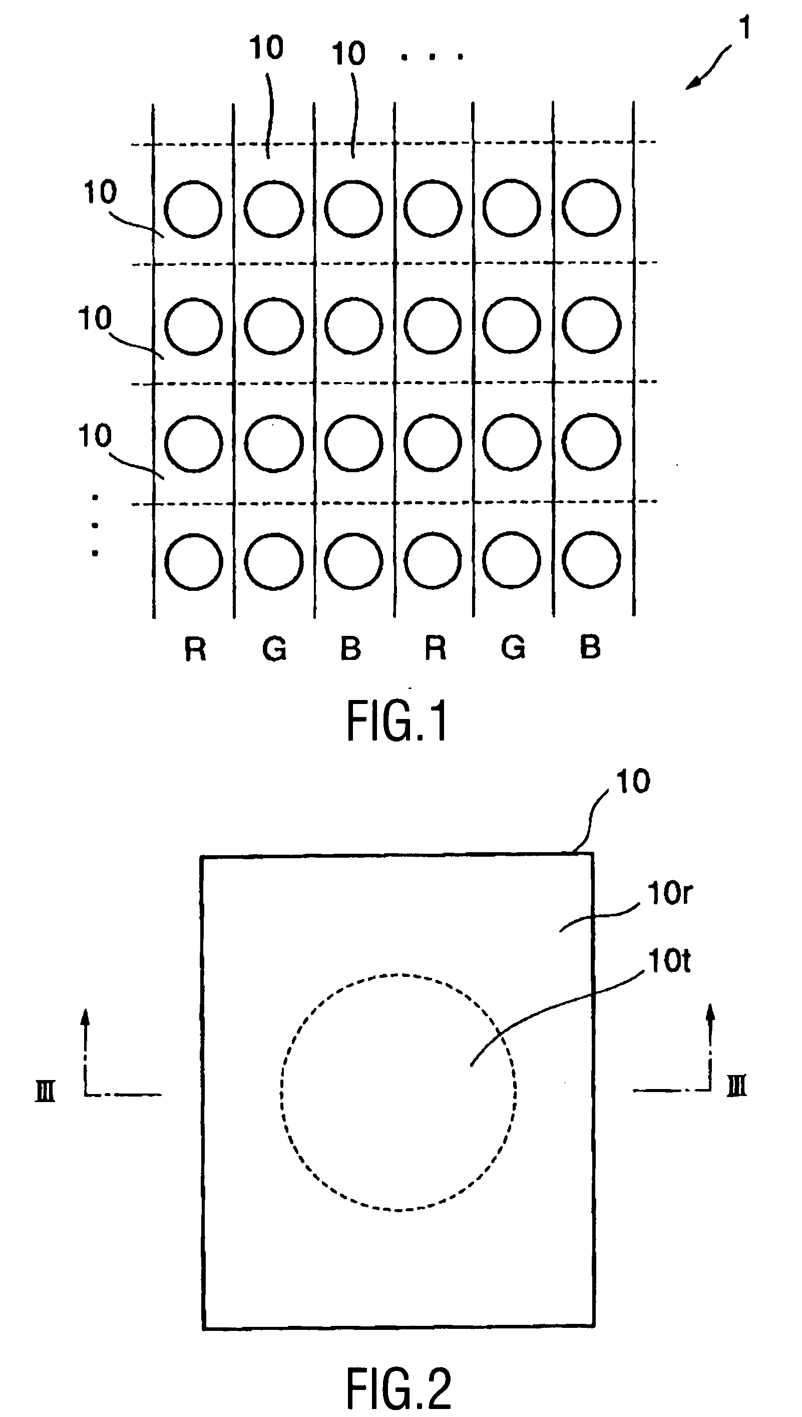
[0037] FIG. 1 illustrates a general plan view of a color filter 1 employed in a liquid crystal display device of a first embodiment according to the present invention.

[0038] The color filter 1 is partitioned into longitudinal coloring areas each of which extends in a vertical direction of a display screen, and which have coloring matters of red (R), green (G) and blue (B), respectively. These longitudinal coloring areas are cyclically arranged in order of R, G and B in a horizontal direction on the display screen. One longitudinal coloring areas may be further divided in a vertical direction, and each of the divisional portions corresponds to a pixel. The divisional portion will be referred to as a pixel area part 10 hereinafter. It is noted that although the longitudinal coloring areas are partitioned in a vertical direction by dashed lines as shown in FIG. 1, the pixel area parts 10 (the pixel area parts 10 vertically aligned) of one longitudinal coloring area...

embodiment 2

[0049] [Embodiment 2]

[0050] A second embodiment that is more advanced than the above-described embodiment is shown in FIG. 4.

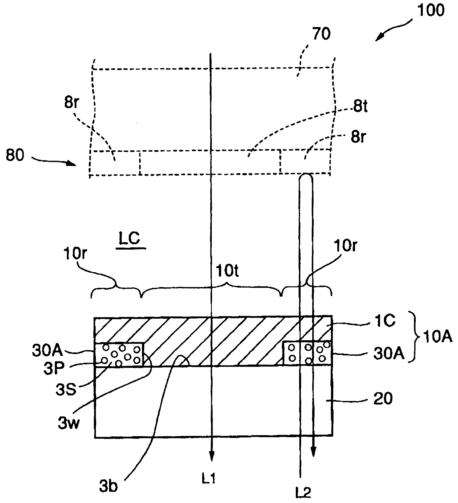
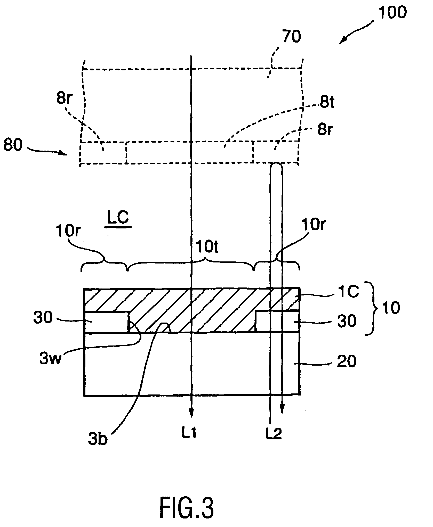
[0051] A pixel area part 10A of a color filter in FIG. 4 comprises a layer 30A as a step-forming layer which includes an optically transmissive base material (or matrix material) 3S and a large number of optically transmissive particles 3P having a refractive index different from that of the base material and being scatteredly added to the base material. The other structural features are the same as those of FIG. 3.

[0052] The layer 30A has a function of diffusing (or scattering) a light ray incident thereon and passing therethrough. This function is mainly based on a difference between the refractive indexes of the base material 3S and the particles 3P and also depends on parameters such as shapes, sizes, density and / or distributional condition of the particles in the base material. In order to prevent unfavorable coloring caused by interaction, the particles ...

embodiment 3

[0057] [Embodiment 3]

[0058] In the first and second embodiments, there was described the examples where the surface of the coloring layer 1C is sufficiently flattened. If the surface of the coloring layer 1C is flat, planes of incidence for light rays on the surface is uniformly flattened within a pixel. This leads to advantages in respect of optical performance for coloring effect or the other respects.

[0059] However, actually in order to make the surface of the coloring layer 1C to be flat, an entire thickness of the coloring layer 1C has to be considerably large or has to be formed using a special material for the coloring layer 1C. The first region 10t forms a recess-shaped portion defined by a pattern of the transparent resin layer 30 and a step (or difference in level) is made on a face on which the coloring layer 1C is deposited so as to correspond to the first region 10t. So, if the coloring layer 1C is deposited on the face and then treated for finishing (cured or the like)...


PUM

PropertyMeasurementUnit
thicknessaaaaaaaaaa
shapeaaaaaaaaaa
circle shapeaaaaaaaaaa

Abstract

An object of the invention is to provide a color filter and a liquid crystal display device using it, which can acquire uniform color purity within a pixel. A color filter for coloring the first light ray L1 having a unidirectional optical path and the second light ray L2 having a bidirectional optical path for each pixel. This filter comprises: a step-forming layer of optically transmissive material, which can be supported by a base layer 20, and which is patterned for a pixel to form at least one recess-shaped portion having a bottom face 3b of a predetermined shape corresponding to an area wherein the first light ray L1 is caused to be transmitted and a wall face 3w of a predetermined height; and a coloring layer 1C deposited on the step-forming layer 30 and the recess-shaped portion for coloring the first and second light rays.

Description

[0001] 1. Field of the Invention[0002] The present invention relates to a color filter. The present invention also relates to a liquid crystal display device employing a color filter.[0003] In particular, the present invention relates to a color filter which handles a first light ray and a second light ray. The first light ray has such a unidirectional optical path that the light ray incident from one principal plane side of the filter passes through the filter only once to be colored and is guided to the other principal plane side of the filter. The second light ray has such a bi-directional optical path that the light ray incident from the other principal plane side of the color filter passes through the filter to be colored and the passed light ray is reflected by an optical reflective element or the like disposed in the one principal plane side to enter the filter again and pass to be colored, and comes back to the other principle plane side. The invention also relates to a meth...

Claims


Application Information

Patent Timeline
Patent Type & Authority Applications(United States)
IPC IPC(8): G02B5/02G02B5/08G02B5/20G02B5/22G02F1/1335
CPCG02B5/22G02F1/133555G02F1/133514
Inventor II, MIHO
Owner TPO HONG KONG HLDG
Why Eureka
Try Eureka