Switched reactance modulated E-class oscillator

a technology of reactance modulation and oscillator, which is applied in the direction of oscillation generator, pulse technique, therapy, etc., can solve the problems of significant physical limits on power, data transmission and packaging, stringent requirements, etc., and achieve the effect of reducing the frequency of the drive signal, reducing the frequency of the oscillation, and reducing the oscillation frequency of the tank circui

Inactive Publication Date: 2004-09-23
ALFRED E MANN INST FOR BIOMEDICAL ENG AT THE UNIV OF SOUTHERN CALIFORNIA
View PDF57 Cites 14 Cited by
  • Summary
  • Abstract
  • Description
  • Claims
  • Application Information

AI Technical Summary

Problems solved by technology

Achieving such efficiency, however, can be problematic.
Their small size can result in significant physical limits on power, data transmission and packaging.
The small, narrow shape of many BIONs may result in stringent requirements for wireless power, data transmission and the electromechanical assembly.
Developing solutions to meet these requirements may be difficult.
For example, the inductive coupling between a primary inductive coil within an extracorporeal antenna utilized to power a BION and a small, secondary inductive coil within the BION itself may be difficult to establish and maintain within the stringent requirements of the BION's power, data transmission, and electromechanical assembly.
However, the BION's small size may limit the BION's receiving coil size.
However, excessive power dissipation may be undesirable.
However, designing an appropriate oscillator to generate sufficient field strength can be problematic.
Conventional A-Class amplifiers may not be efficient enough for field use, as they can exhibit significant power dissipation.
However, it may be unclear how to effectively utilize a Class E oscillator in a BION application, where both power efficiency and data transmission are often needed.
These requirements can be in conflict, as power efficiency often requires highly resonant operation of the Class E oscillator, while data transmission often requires rapid modulation of the Class E oscillator.
With respect to the rapid modulation, a problematic feature of the Class E oscillator, in BION applications, can be that both the position and duration of the drive pulse are critical.
For a coil frequency of 2 MHz, any drive pulse over 125 ns can cause excessive power dissipation in the switch without significantly increasing the energy in the coil.
However, producing various pulse widths can require additional components that increase the cost and size of the coil driver assembly, which can be impractical in BION applications.
Using a Class E oscillator in BION applications can cause additional problems.
Such deformities can cause fluctuations in the inductance of the external coil, and a Class E oscillator may not inherently compensate for such fluctuations.
This type of construction can make a typical Class E oscillator unsuitable for BION applications.
Further, complicated circuitry can be required to change pulse width for achieving desired AM modulation, when utilizing a typical Class E oscillator.
Changes in pulse width can be undesirable because they can cause significant degradation of efficiency, something a battery-operated BION may have limited capacity to endure.

Method used


Image

  • Switched reactance modulated E-class oscillator
  • Switched reactance modulated E-class oscillator
  • Switched reactance modulated E-class oscillator

Examples


Embodiment Construction

[0041] In the following description of illustrative embodiments, reference is made to the accompanying drawings. It is to be understood that other embodiments may be utilized and structural and functional changes may be made without departing from the scope of the concepts that are presented.

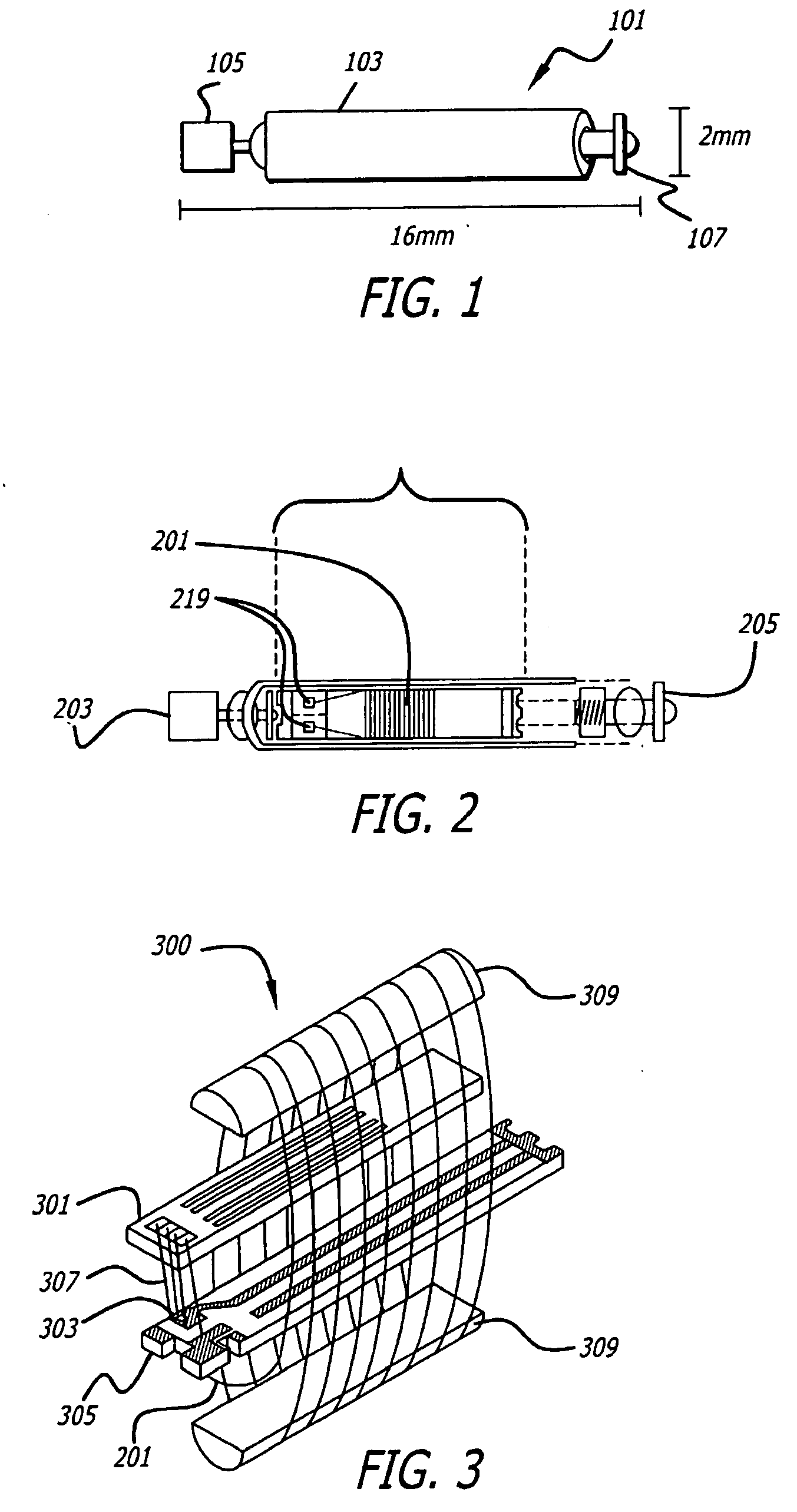
[0042] FIG. 1 illustrates a BION 101. It may be encased in a glass sheath 103 and may have two electrodes, a Ta electrode 105 and an Ir electrode 107. BION 101 may have a size of about 2 mm in diameter and 16 mm in length. The small size may allow the BION to be implanted by injection in an outpatient procedure that may be performed by a physician. The size may allow the BION to be placed in a small, deep, or hard-to-reach muscle that may be difficult to stimulate effectively from the skin surface. The small size and wireless nature of the implantable BION may minimize the threat of infection, skin breakdown, and tissue damage. Other types of implants may be too large, particularly in areas wher...


PUM


Abstract

A modulated Class E oscillator. In one embodiment, the modulated Class E oscillator may achieve high coil currents (about 1 A) and voltages (about 500 V) with low power components. Current may be injected when the oscillating current in the inductor passes through zero. A detector circuit may be used to trigger the current injection at the appropriate instant regardless of changes in the resonant frequency of the system. Its phase can be adjusted to compensate for propagation delays in the drive circuitry, while amplitude modulation is accomplished by switching in additional reactive conductance to increase the current injected into the tank circuit. Frequency modulation is accomplished in an alternate embodiment. The oscillator can also lock to an external reference signal and be phase modulated.

Description

[0001] This application is a continuation-in-part of U.S. patent application Ser. No. 10 / 180,882, filed Jun. 26, 2002 and patent application Ser. No. 09 / 973,486, filed Oct. 5, 2001. This application is also based upon and also claims priority to U.S. provisional applications Ser. No 60 / 459,908, filed Mar. 21, 2003, and Ser. No. 60 / 462,215, filed Apr. 11, 2003. This application is also related to U.S. Provisional Application Ser. No. 60 / 238,488, filed Oct. 6, 2000. The content of all of these applications are incorporated herein by reference.[0002] 1. Field[0003] This application relates to drive coils that generate a magnetic field to supply power and operational commands to a remote receiving coil. This application also relates generally to E-class oscillators.[0004] 2. Related Art[0005] Many applications require or would benefit from improved efficiency in L-C tank circuit oscillations. Achieving such efficiency, however, can be problematic. One problem is now presented in the con...

Claims


Application Information

Patent Timeline
Patent Type & Authority Applications(United States)
IPC IPC(8): A61N1/08A61N1/372
CPCA61N1/08A61N1/3727A61N1/37211
Inventor MOORE, WILLIAM HENRY
Owner ALFRED E MANN INST FOR BIOMEDICAL ENG AT THE UNIV OF SOUTHERN CALIFORNIA
Why Eureka
Try Eureka