
Semiconductor nanoparticles coated with electroactive polymers

a technology of electroactive polymer and nanoparticles, which is applied in the direction of silicon compounds, semiconductor/solid-state device details, cellulosic plastic layered products, etc., can solve the problems of limited stability of such bonds, particle use, and large amount of polymer attached to particles, and achieves the effect of high oxidation potential

Inactive Publication Date: 2004-10-07
AGILENT TECH INC
View PDF7 Cites 6 Cited by
  • Summary
  • Abstract
  • Description
  • Claims
  • Application Information

AI Technical Summary

Benefits of technology

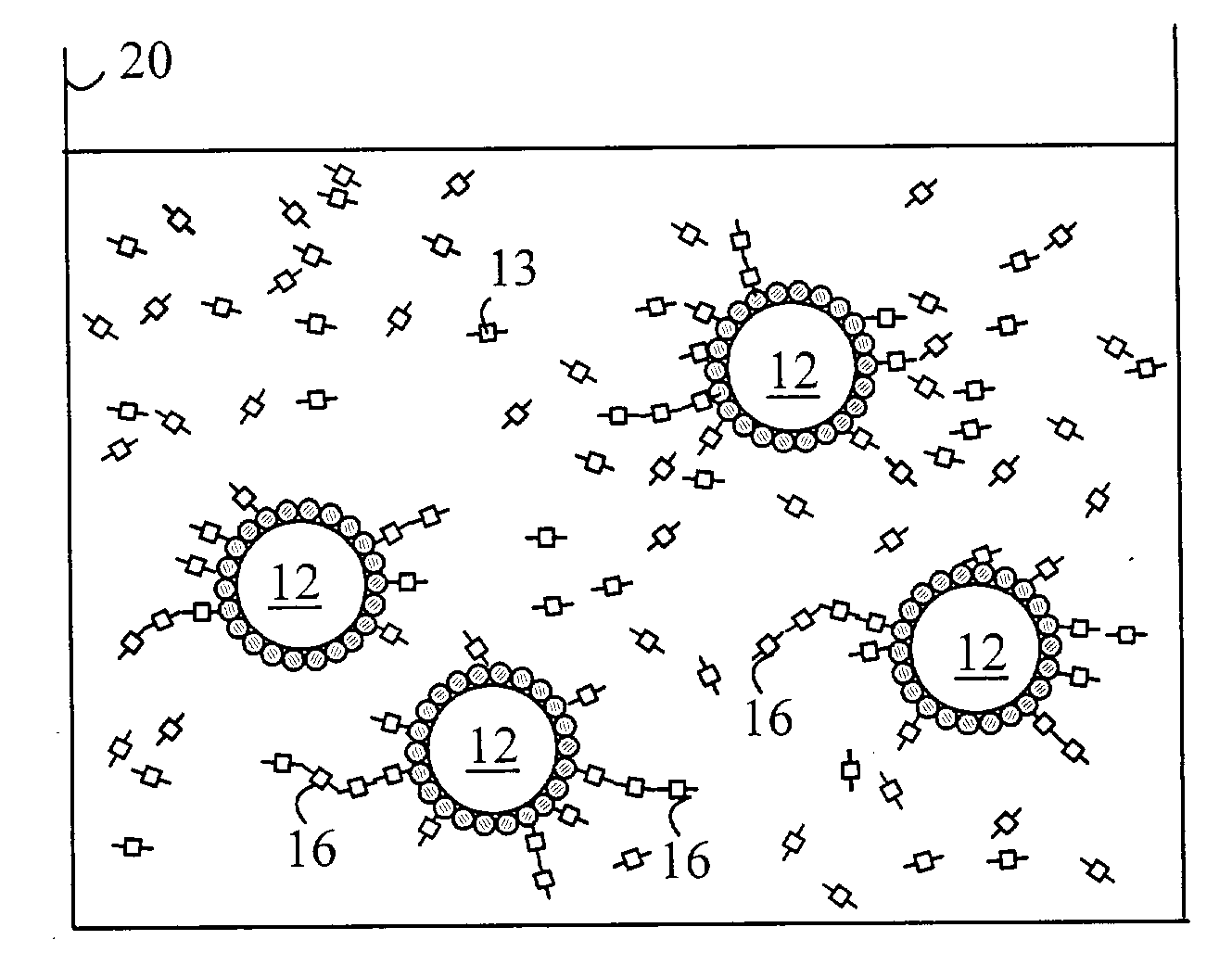
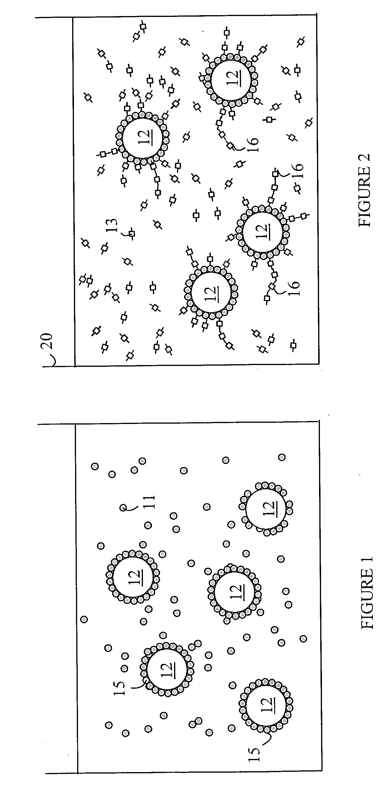
The present invention is a method for coating particles with a polymer that alters the energy bandgap of the particles. The particles are first placed in a solution of a monomer that forms a self-assembling monolayer on the particles, and then suspended in a solution containing a chemical species and an initiator for oxidative polymerization. The chemical species forms a homopolymer that is covalently bound to the monomers. The coated particles can have useful surface chemistries and can be used in various applications such as electronics, sensors, and biomedical devices.

Problems solved by technology

However, the band gap energy of undoped Ti0.sub.2, which is .about.3.2 eV, prevents such undoped particles from being used in a number of applications.
Unfortunately, the amount of polymer that is attached to the particles depends on a number of factors that are not easily controlled.
While the coupling of colloidal Ti0.sub.2 with specific organic molecules is very simple, the stability of such bonds is limited.
These bonds are associated with "crystal defects" on the surface of the particles, and hence, the density of these bonds is low.
Furthermore, the density of these bonds is a function of particle size, which further limits the applicability of this procedure.
Unfortunately, only a limited number of sensitizer molecules can be so absorbed on the surface of the Ti0.sub.2 particles, and hence, this technique has a sensitization yield that is insufficient for many applications.

Method used


Image

  • Semiconductor nanoparticles coated with electroactive polymers
  • Semiconductor nanoparticles coated with electroactive polymers

Examples


Embodiment Construction

[0008] The present invention includes a method for modifying the surface of a metal oxide particle in a manner that will allow other organic molecules to be incorporated on the surface of the particle with greater density and better stability than the methods described above. The manner in which the present invention provides its advantages can be more easily understood with reference to an exemplary coated Ti0.sub.2 particle that is prepared by the method of the present invention. Modification of Ti0.sub.2 particles with polymers that are more hydrophobic than Ti0.sub.2 enables particles to be stably dispersed in organic solvents. For example, Ti0.sub.2 particles modified with poly(3,4 dioxyethylenethiophene)(PEDOT) can be dispersed in methanol and acentonitrile for over 2 weeks. Such modified particles can be selectively deposited to form a Ti0.sub.2-polymer matrix on the surface of an electrode and will be electroactive because of the conjugated PEDOT polymer molecules.

[0009] The...


PUM

PropertyMeasurementUnit
MWaaaaaaaaaa
semiconductoraaaaaaaaaa
semiconductingaaaaaaaaaa

Abstract

A method for coating particles and the coated particles obtained thereby are disclosed. The particles are first placed in a solution of a first monomer that forms a self-assembling monolayer on the particles thereby forming coated particles. The coated particles are then suspended in a second solution that includes a chemical species and an initiator for oxidative polymerization. The chemical species has a higher oxidation potential than the monomers. In addition, the chemical species form a homopolymer in the presence of the initiator that is covalently bound to the first monomers. Particles of semiconductors such as Ti02, Si02, Sn02, Al203 can be coated with polymers that alter the bandgap energy of the semiconducting particles and / or provide other useful surface chemistries.

Description

[0001] The present invention relates to semiconducting particles having photoactive characteristics.[0002] Presently, photoactive semiconductor nanoparticles are potentially useful in constructing solar cells and for use as labels in various bioassays. Particles of titanium dioxide (Ti0.sub.2) are attractive candidates for such applications. However, the band gap energy of undoped Ti0.sub.2, which is .about.3.2 eV, prevents such undoped particles from being used in a number of applications. Accordingly, various schemes for reducing the band gap energy of such particles have been suggested. For example, in one application, particles of a titanium oxide are mixed with the monomer for conjugated polymer, then the monomer is polymerized with added oxidant. The composite particles of inorganic metal oxides and electroactive polymers have potential uses in photovoltaic cells. Unfortunately, the amount of polymer that is attached to the particles depends on a number of factors that are not...

Claims


Application Information

Patent Timeline
Patent Type & Authority Applications(United States)
IPC IPC(8): B32B5/16B32B19/00
CPCB82Y30/00Y10T428/2998C01G9/02C01G23/047C09C1/3063C09C1/3072C09C1/3669C09C1/3676C09C3/08C09C3/10H01L51/0036H01L51/4226Y10S977/89Y10S977/773Y10S977/847Y02E10/549Y10T428/2991C01B33/146H10K85/113H10K30/151C01P2004/84
Inventor INAOKA, SEIJI
Owner AGILENT TECH INC
Learn More