
Bicycle crank arm

Inactive Publication Date: 2004-10-14
CRANK BROS INC
View PDF26 Cites 65 Cited by
  • Summary
  • Abstract
  • Description
  • Claims
  • Application Information

AI Technical Summary

Benefits of technology

[0019] It is an object of the present invention to provide a bicycle crank arm with a high strength to weight ratio.
[0020] It is another object of the present invention to provide a bicycle crank arm that is relatively simple and inexpensive to make.
[0021] It is another object of the present invention to provide a bicycle crank arm that is relatively easy to produce in large quantities.

Problems solved by technology

This can cause reliability problems for any joints or welds that are near the crank spindle.
All of these processes to make tubular cross sections are relatively expensive.
The proprietary processes require expensive research and development, expensive proprietary equipment, and careful process control.
Also, there are limits to how carefully the hollow area can be controlled, so there are limits to how efficient the crank can be designed.
Welding two shells together is a labor intensive process, and for aesthetics, usually requires expensive post finishing work to hide the aesthetics of the weld.
Welding a tube of steel or titanium or aluminum to end components is expensive because it requires carefully fixturing and welding many components together (i.e.: welding the tube to a threaded boss and end cap on one end, and welding the other end of the tube to a spider assembly).
Welding can also decrease the strength of the material near the weld.
The transitions from the solid end portions to the tubular portion of existing crank arms are often abrupt and with sharp edges or corners.
Some extremely expensive high performance cranks are made of thin-walled welded tubular chromoly, steel or titanium.
However, aluminum has some disadvantages as a material for crank arms.
For example, aluminum is a low density metal that is susceptible to damage from impacts with rocks and such, common during mountain biking.
Aluminum has poor fatigue resistance compared to steel and titanium, and aluminum is difficult to forge or cast with a hollow interior.
CNC machining is expensive because it requires a relatively expensive CNC mill, a relatively skilled programmer, it wastes a significant amount of material, it is a relatively slow process, and the surface finish is rough.
Carbon fiber (and similar) is very expensive because the materials are expensive, and the process is slow and difficult and requires highly skilled workers.
Welding can be expensive and can weaken the material in the vicinity of the weld.
Higher end crank arms (whether solid aluminum or hollow) typically require extensive finishing (polishing or CNC work) for aesthetic reasons and this adds substantially to the cost.
Locating a joint near a region of maximum bending moment increases the likelihood of failure unless additional material thickness is provided.
Bezin's crank arm also suffers from an abrupt transition where the thin tube meets the solid lug, producing a stress concentration.
There is no provision for optimizing the configuration of the components to reduce the stress concentration.
If the crank arm is fabricated using a welding process, it is difficult to obtain proper weld penetration in the heavy lug without overheating the thin tube.
Girvin discusses configuring the redundant doubler plate to reduce stress concentration at the upper welded interface, but does not address the abrupt transition where the tube otherwise meets the lug.
Girvin discusses using a tapered tube to increase the section modulus in regions of high stress, but does not provide for a varying wall thickness.
Girvin does not address the issue of satisfactorily welding a thin-wall tube to a more massive lug.
Girvin provides no way to adapt to lightweight alloys.
The welded surfaces are substantially parallel to the long axis of the crank arm, which results in a relatively large weld area, long processing time and high fabrication expense.
There is relatively little space enclosed by the box-beam, owing to the relatively thick walls, which results in a heavy, stiff and rigid crank arm.
Yamanaka discusses shaping the long axis of the groove into a "ship hull shape" to better distribute the stresses in the crank arm, but provides no other means of optimizing the crank arm.
Yamanaka's crank arm, however, requires a relatively expensive and complex manufacturing process and has limited control over the wall sections (and thus the maximum size and shape of the hollow cavity).
For example, the single-use cores would be expensive and time consuming to make.
Mizobe's crank arm, however, requires a relatively expensive and complex manufacturing process, has limited control over the wall sections (and thus the maximum size and shape of the hollow cavity), and has the added weight of an internal filler.
This embodiment suffers the same disadvantages as the first embodiment except for the lack of filler material weight and requires the additional step of removing the filler material.
Chiang describes in his U.S. Pat. No. 6,508,002 that such a prior art bicycle crank arm as described in his '923 patent is neither cost-effective nor durable in view of the fact that the process of fastening the head portion and the pedal hole portion with the hollow crank body is rather time-consuming and that the head portion and the pedal hole portion are apt to break away from the hollow crank body.
Chiang's crank arm, however, requires a relatively expensive and complex manufacturing process and has limited control over the wall sections (and thus the maximum size and shape of the hollow cavity).
The box will feel flimsy and weak.

Method used


Image

  • Bicycle crank arm
  • Bicycle crank arm
  • Bicycle crank arm

Examples


Embodiment Construction

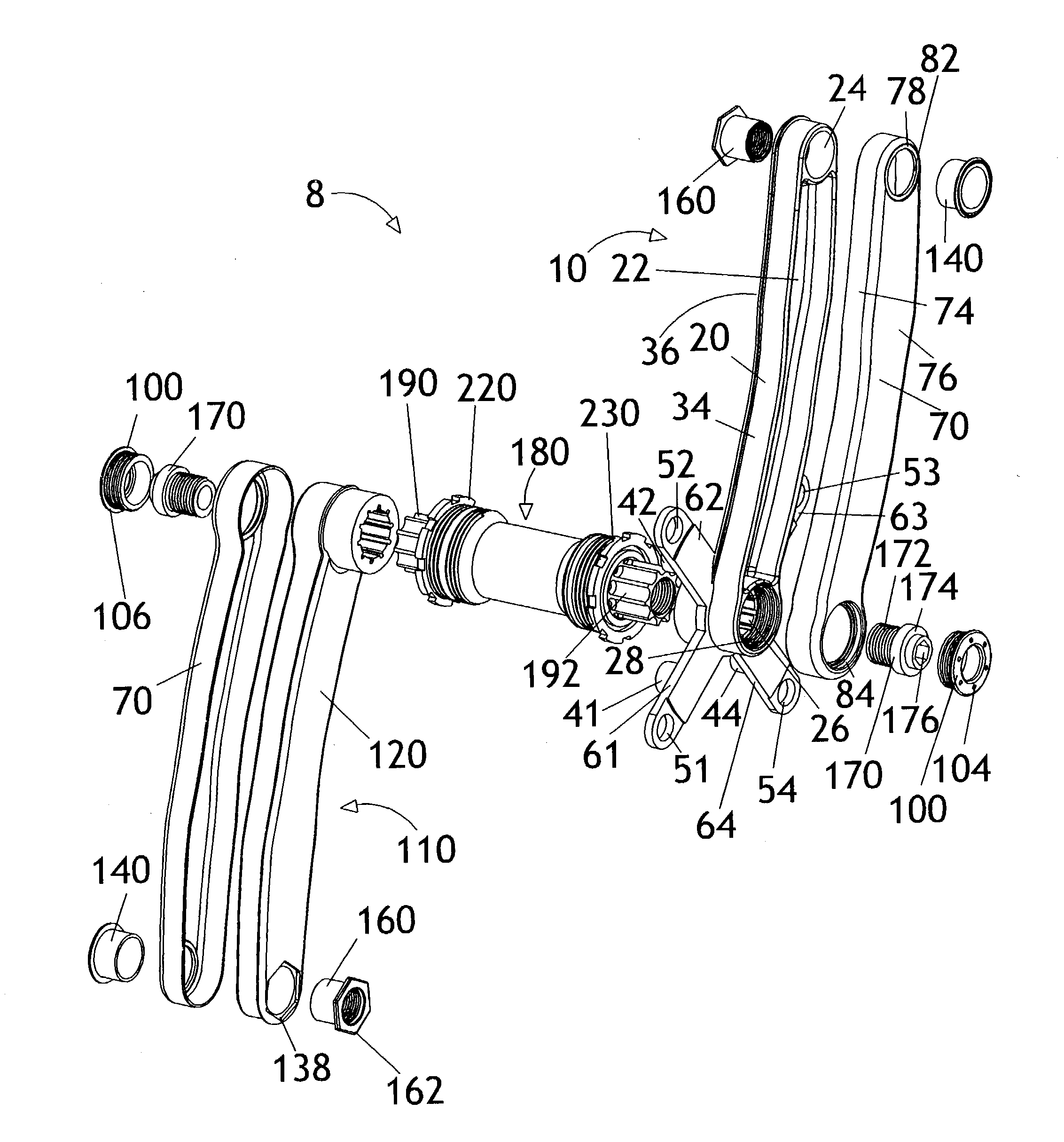
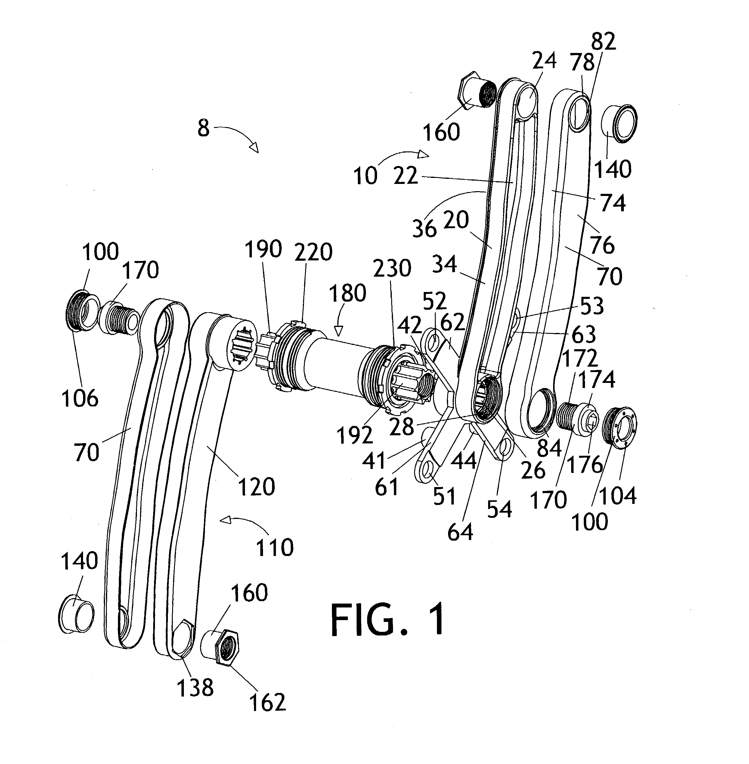
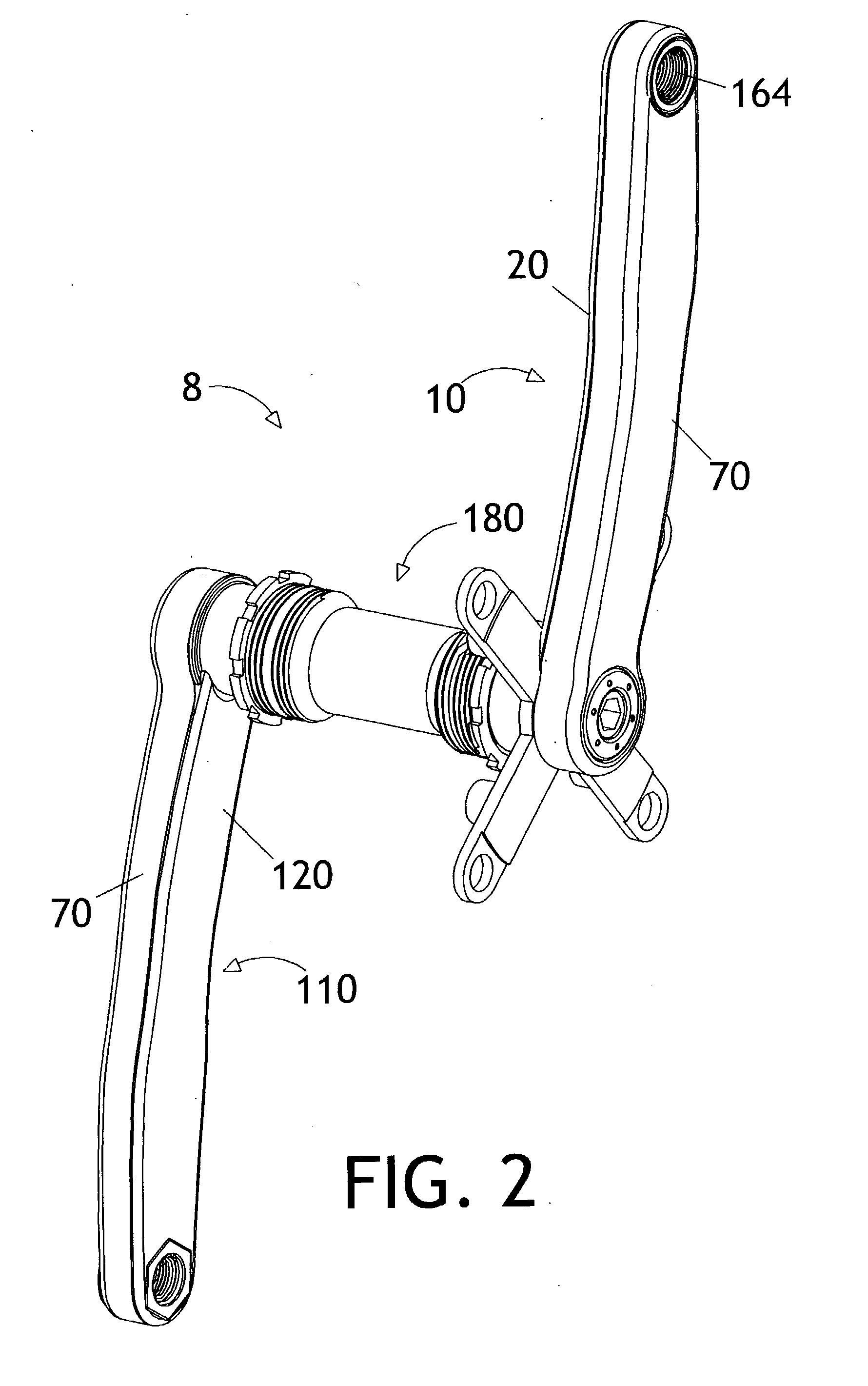
[0064] The preferred embodiment of the present invention may be understood by referring to FIGS. 1-8. It will be seen that a bicycle crank 8 comprises a drive side crank arm 10, a conventional bottom bracket 180 and a non-drive side crank arm 110. The drive side crank arm 10 comprises a base 20, a cover 70, fittings 100, 140 and 160 and screw 170. The typical bottom bracket 180 comprises a spindle 190, a body 220, a ring 230 and bearings 240. The non-drive side crank arm 110 is comprised of a base 120, a cover 70, fittings 100, 140, and 160 and a screw 170. Bases 20 and 120 are preferably made by die casting or forging out of aluminum or magnesium and has a side wall 34 and a back wall 36, to form recess 22. Cover 70 is preferably stamped out of steel or titanium and has a side wall 74 and top wall 76. When cover 70 is placed over base 20, recess 22 becomes a hollow space 202 (see FIG. 8). Cover 70 is held firmly to base 20 on one end by fittings 140 and 160 and on the other end by ...


PUM


Abstract

A hollow bicycle crank arm has a central tubular portion to reduce weight and two mounting-boss portions for mounting a crank spindle and pedal during use. A crank arm base is forged or cast with a relatively thin back and sides, preferably out of aluminum or magnesium. The crank arm base has a generally C-shaped cross section. An arm cover has a top and sides and is made from stamped steel or titanium. The cover is placed over the open crank arm base to enclose a significant hollow section. The stamped arm cover does not require any threading or welding. It can be made using a very inexpensive stamping process. The crank arm can be made using relatively inexpensive traditional manufacturing processes such as die casting or forging.

Description

[0001] 1. Field of the Invention[0002] The present invention relates generally to structural components subjected to flexural and torsional loads, and more specifically, to a bicycle crank arm of improved strength-to-weight ratio and reliability.[0003] 2. Background Art[0004] Many methods have been used to try to create a lighter and stiffer crank set. The rider transfers power through the pedals, which are screwed into the crank arms. The force from the rider's legs causes the crank arms to be placed under bending as well as twisting loads. A transverse shear (beam shear) force also results from the pedaling force. Because it is laterally offset from the arm, the pedaling force also tends to twist the arm about it long axis. The applied bending moment varies from near-zero at the pedal to a maximum value at the crank spindle. This can cause reliability problems for any joints or welds that are near the crank spindle.[0005] For stiffness, the ideal crank arm cross section has a larg...

Claims


Application Information

Patent Timeline
IPC IPC(8): G05G1/30
CPCY10T74/2164B62M3/00
Inventor HERMANSEN, FRANKWINEFORDNER, CARL
Owner CRANK BROS INC
Learn More