Optical recording medium and data recording apparatus for recording data in the same

a technology which is applied in the field of optical recording medium and data recording apparatus for recording data in the same, and can solve the problems of small difference in optical constant between before and after data recording, degraded storage reliability of optical recording medium, and erased record marks

Inactive Publication Date: 2004-10-28
TDK CORPARATION
View PDF6 Cites 28 Cited by
  • Summary
  • Abstract
  • Description
  • Claims
  • Application Information

AI Technical Summary

Problems solved by technology

Specifically, in the case where the crystallization temperature of a chalcogen system alloy contained in a recording layer of an optical recording medium is low, the storage reliability of the optical recording medium may be degraded because there is a risk of record marks being erased when data are repeatedly reproduced from the optical recording medium or the optical recording medium is stored in a high-temperature atmosphere.
However, when the recording layer 14 is too thin, the difference in the optical constants between before and after data recording becomes small and a reproduced signal having a high level (C/N ratio) cannot be obtained.
On the other hand, when the recording layer 14 is too thin, since the crystallization speed becomes markedly low, it is difficult to directly overwrite data and it is difficult to control the thickness of the recording layer 14 when it is formed.
In the case where the thickness of the heat radiation layer 16 is thinner tha

Method used


Image

  • Optical recording medium and data recording apparatus for recording data in the same
  • Optical recording medium and data recording apparatus for recording data in the same
  • Optical recording medium and data recording apparatus for recording data in the same

Examples


working example 1

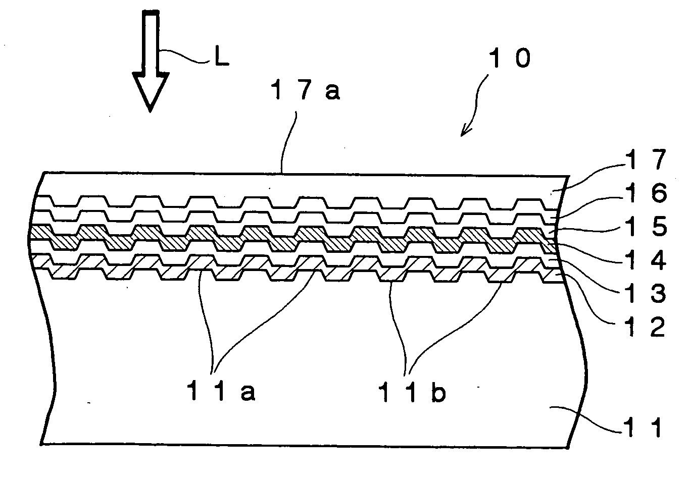
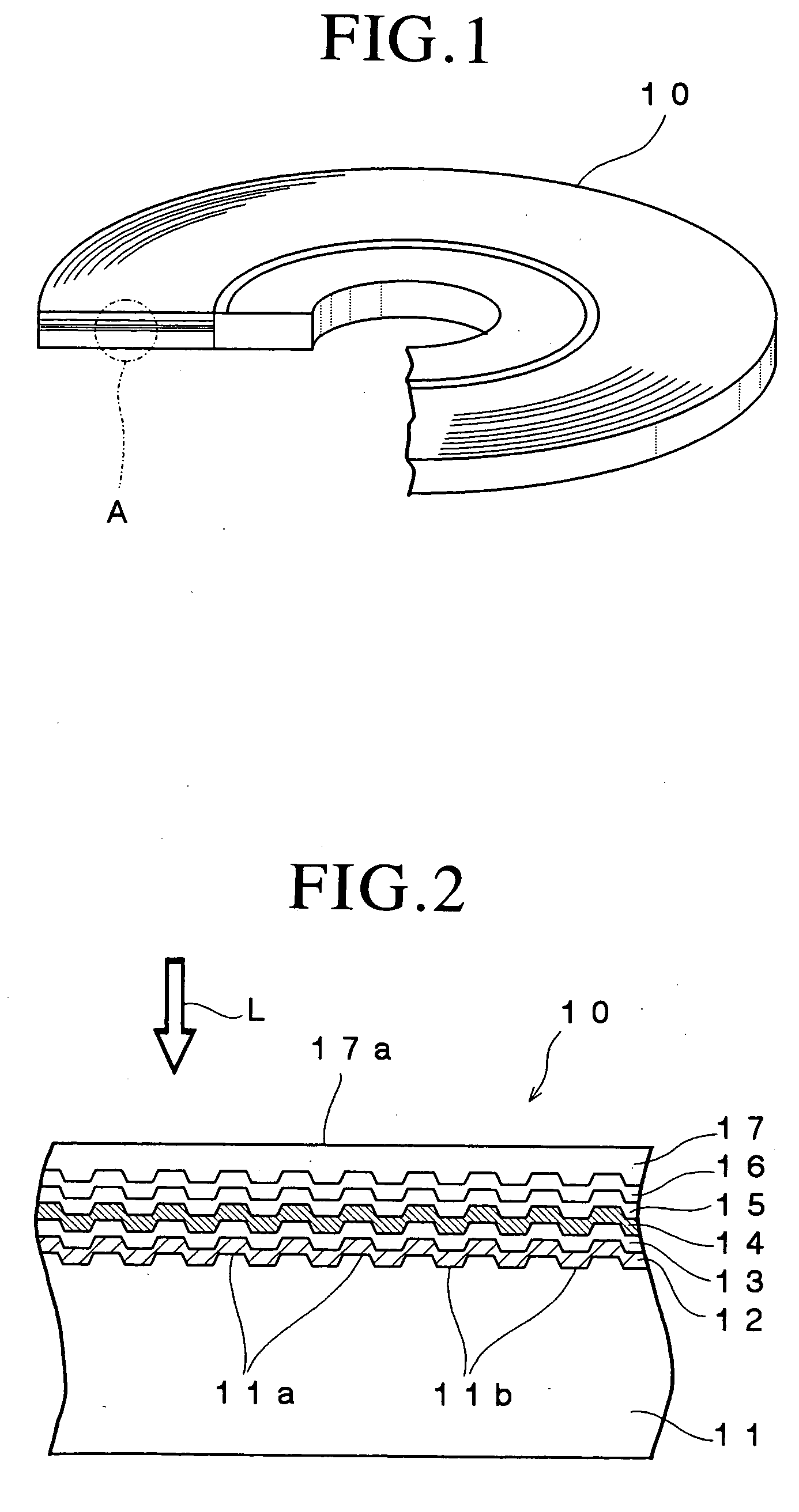
[0139] An optical recording medium sample # 1 was fabricated in the following manner.

[0140] A substrate of polycarbonate having a thickness of 1.1 mm and a diameter of 120 mm and formed with grooves and lands on the surface thereof was first fabricated by an injection molding process.

[0141] Then, the substrate was set on a sputtering apparatus and a reflective layer consisting of an alloy containing 90 atomic % or more of Ag and added with Pd and Cu and having a thickness of 100 nm, a second dielectric layer consisting of a mixture of ZnS and SiO.sub.2 and having a thickness of 4 nm, a recording layer containing 74.0 atomic % of Sb, 16.7 atomic % of Te, 4.7 atomic % of Ge, 3.7 atomic % of Tb and 0.9 atomic % of In and having a thickness of 14 nm, a first dielectric layer consisting of the mixture of ZnS and SiO.sub.2 and having a thickness of 30 nm and a heat radiation layer containing 90 atomic % of more of aluminum nitride and having a thickness of 100 nm were sequentially formed ...


PUM

PropertyMeasurementUnit
Thicknessaaaaaaaaaa
Thicknessaaaaaaaaaa
Thicknessaaaaaaaaaa

Abstract

An optical recording medium includes a recording layer, a first dielectric layer disposed on the side of a light incidence plane through which the laser beam enters with respect to the recording layer, a second dielectric layer disposed on the side opposite to the light incidence plane with respect to the recording layer, a heat radiation layer disposed on the side of the light incidence plane with respect to the first dielectric layer and a reflective layer disposed on the side opposite to the light incidence plane with respect to the second dielectric layer, the recording layer containing a phase change material represented by an atomic composition formula: SbaTebGecTbd, where a is equal to or larger than 63 and equal to or smaller than 78, c is equal to or larger than 2 and equal to or smaller than 10, d is equal to or larger than 3 and equal to or smaller than 15, (a+d) is equal to or larger than 75 and equal to or smaller than 82 and a/b is equal to or larger than 3.3 and equal to or smaller than 4.9, in an amount equal to or more than 95 atomic %. According to the thus constituted optical recording medium, it is possible to simultaneously improve characteristics of recording data therein at a high linear velocity, data reproduction durability and storage reliability.

Description

[0001] The present invention relates to an optical recording medium and, particularly, to a data rewritable type optical recording medium whose characteristics of recording data therein at a high linear velocity can be improved and whose data reproduction durability and storage reliability can be simultaneously improved. The present invention also relates to a data recording apparatus which can record data in an optical recording medium at a high linear velocity and directly overwrite data recorded in an optical recording medium at a high linear velocity.DESCRIPTION OF THE PRIOR ART[0002] Optical recording media such as the CD, DVD and the like have been widely used as recording media for recording digital data. These optical recording media can be roughly classified into optical recording media such as the CD-ROM and the DVD-ROM that do not enable writing and rewriting of data (ROM type optical recording media), optical recording media such as the CD-R and DVD-R that enable writing...

Claims


Application Information

Patent Timeline
IPC IPC(8): B41M5/26G11B7/0045G11B7/125G11B7/24G11B7/243G11B7/257G11B7/258
CPCG11B7/00454G11B7/00456G11B7/243G11B7/2433G11B7/252G11B7/257G11B7/259G11B2007/24312G11B2007/24314G11B2007/24316G11B2007/25708G11B2007/25713
Inventor SHINGAI, HIROSHIKATO, TATSUYAHIRATA, HIDEKI
Owner TDK CORPARATION
Why Eureka
Try Eureka