Visualization stylet for endotracheal intubation

Inactive Publication Date: 2004-10-28
NORTHWESTERN UNIV
View PDF33 Cites 113 Cited by
  • Summary
  • Abstract
  • Description
  • Claims
  • Application Information

AI Technical Summary

Benefits of technology

0029] Additionally, an optional collimator may be positioned in front of the lens. One or more LEDs may be mounted peripherally to the collimator, so that the collimator shields the camera from the light emitted by the LEDs. The collimator both improves the optics of the system by filtering non-parallel incoming light, and shields the camera from direct illumination by the light source(s)

Problems solved by technology

Improper endotracheal intubation is a significant cause of morbidity and mortality during anesthesia.
In some patients, such as obese patients or patients with atypical anatomy, the laryngoscope alone is unable to provide a clear view of the patient's glottis.
So-called "blind intubation" may be attempted in such patients, but the failure rate of blind intubation is high.
Blind intubation frequently leads to trauma and bleeding of the mucosa of the larynx and successful intubation may often require several attempts, slowing critical care and jeopardizing the patient's health.
In some cases, oral intubation is not desirable or practicable and a nasal intubation must be used.
This device provides no direct visualization of the glottis, and supplies only a small improvement over blind intubation.
This device does not fit inside an endotracheal tube.
Use of such fiber-optic devices provides a considerable improvement over blind intubation, but these devices are very complex and expensive, and require extensive training for effective use.
As above, this device is not designed to fit within an endotracheal tube.
The device may include an lumen for ventilation, irrigation or suction, but is not designed to fit within an endotracheal tube.
They are often complex and expensive to manufacture, requiring specialized parts fabrication and assembly.
Due to their cost, they are generally non-dis

Method used


Image

  • Visualization stylet for endotracheal intubation
  • Visualization stylet for endotracheal intubation
  • Visualization stylet for endotracheal intubation

Examples


Example

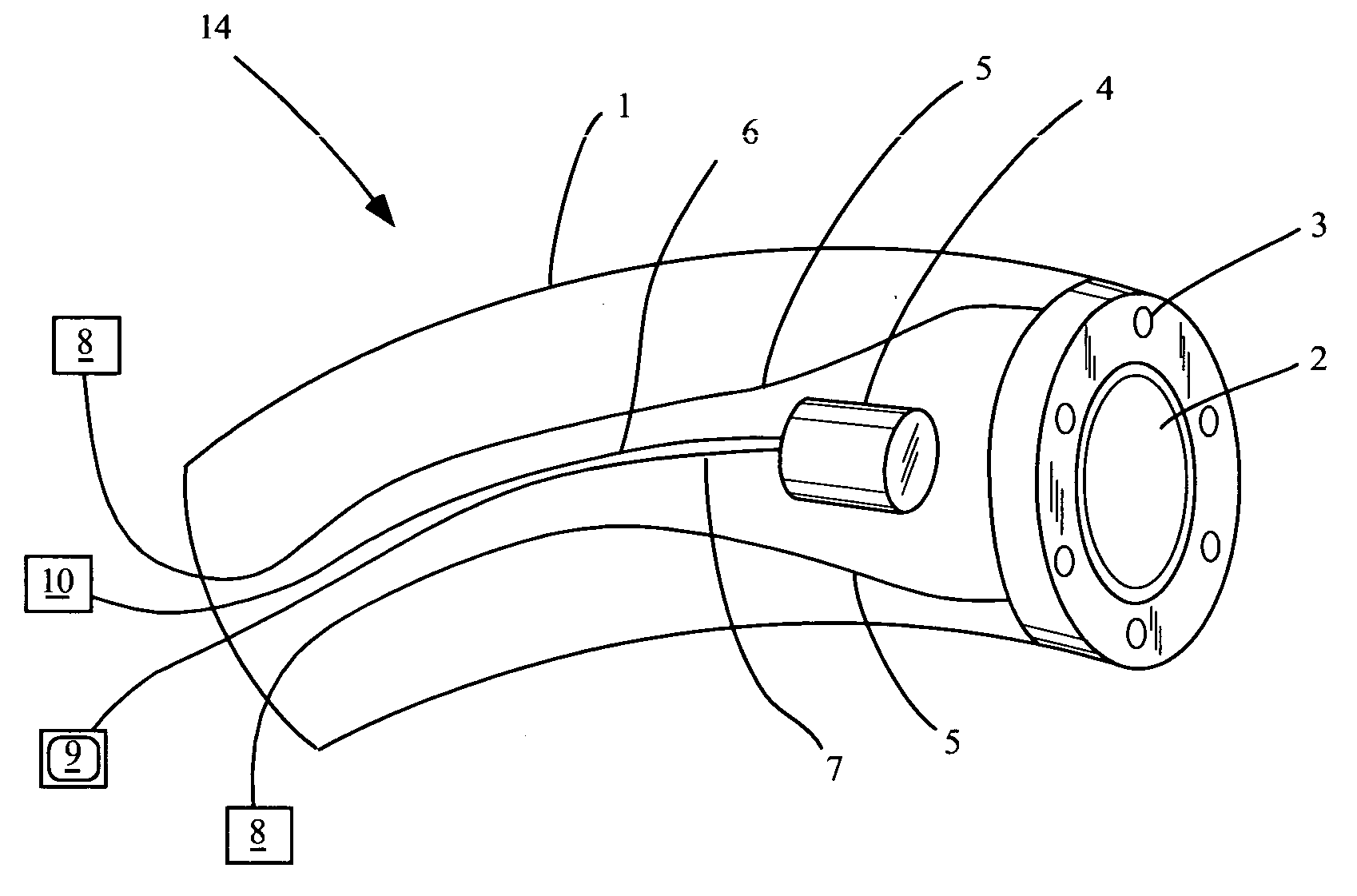
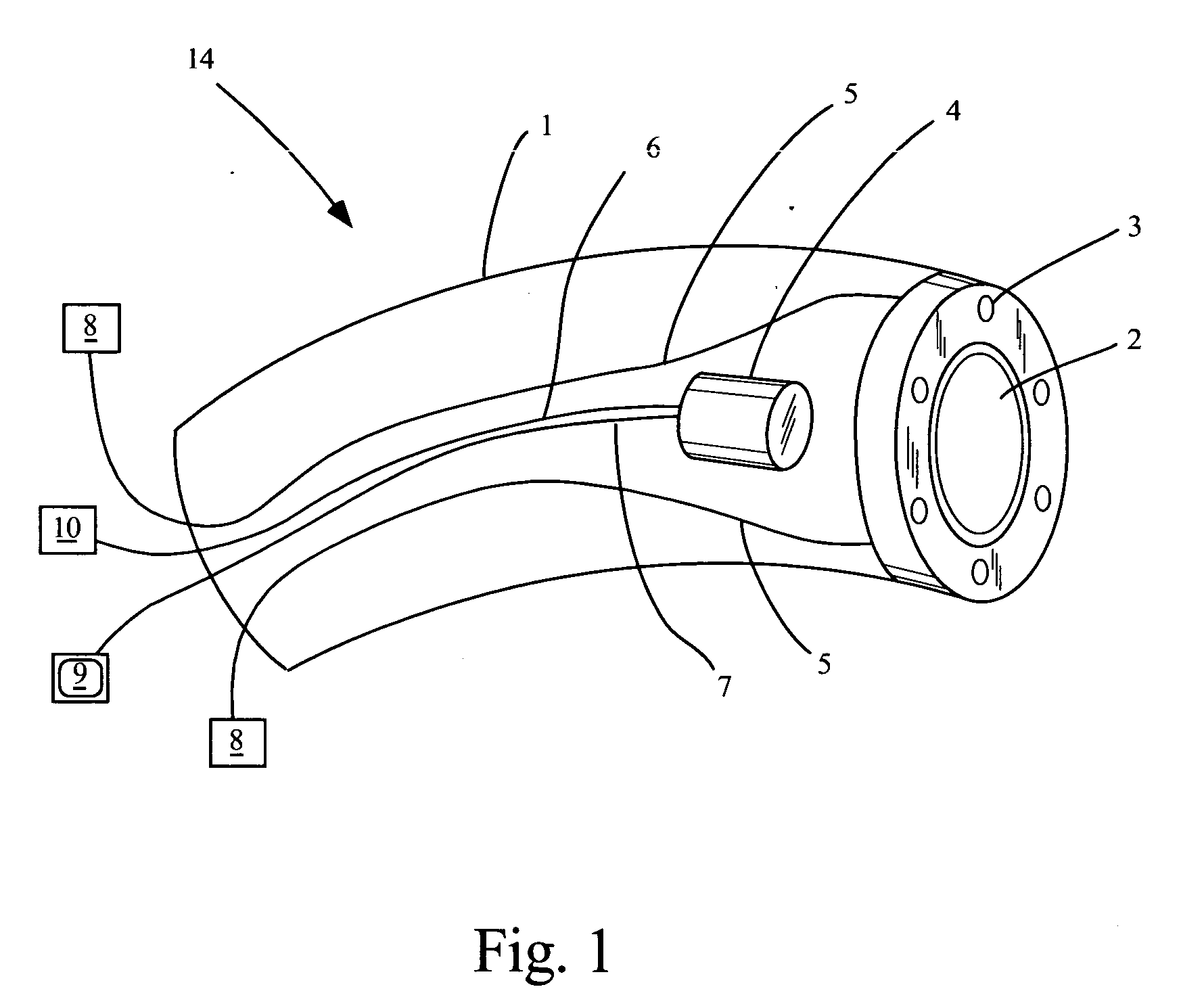
[0062] A specific embodiment of the invention is shown in FIGS. 1 and 2. FIG. 1 shows a schematic representation of the visualization stylet (14). All the elements of the stylet are contained within the lumen of the stylet the (1). The stylet in this particular embodiment has a plurality of white LED lights (3) disposed in a circular pattern at the outside circumference of the distal tip of the stylet, surrounding a central lens (2). The lens focuses light from an image onto the CCD camera (4). The LED lights receive power from one or more power conduits (5) which are electrically connected to a power supply (8). The power supply may be one or more dry cell batteries contained within the body of the stylet, or may be external. The camera, which may be a CCD camera, is centered within the axis of the lumen and slightly behind the distal tip of the stylet tube (1), shielded from the lights (3). The camera receives electrical power from a power supply (10) via a power supply conduit (6...


PUM


Abstract

An endotracheal visualization stylet having a self-contained light source and camera, providing ease of use, economy of manufacture and superior optics.

Description

[0001] This application claims the benefit of co-pending United States provisional application serial No. 60 / 465,976 filed Apr. 28.sup.th, 2003.[0002] The invention relates to medical devices and methods used to visualize the interior anatomy of a body cavity. Specifically, the invention relates to devices used to illuminate and visualize the interior of the oral cavity and larynx during endotracheal intubation.[0003] In the course of providing medical care, particularly in an emergent situation or during anesthesia, it is frequently necessary to insert a tube into a patient's trachea to allow anesthesia and / or for the mechanical ventilation of the lungs of the patient. This procedure is called endotracheal intubation. It is important that the endotracheal tube be placed into the patient's trachea, rather than into the patient's esophagus (or anywhere else), otherwise air will not be delivered to the lungs. For this reason, it is important to be able to visualize the patient's glott...

Claims


Application Information

Patent Timeline
IPC IPC(8): A61B1/233A61B1/267
CPCA61B1/0607A61B1/0676A61B1/0684A61B1/233A61B1/267
Inventor KIMMEL, ZEBADIAHGLASSENBERG, RAYMOND
Owner NORTHWESTERN UNIV
Why Eureka
Try Eureka