Method of making a multi-perforated part out of ceramic matrix composite material

a composite material and multi-perforation technology, applied in the field of ceramic matrix composite material multi-perforation part making, can solve the problems of reducing the effectiveness of air injection through the perforation, destroying the reinforcing fiber, and destroying the fibers,

Active Publication Date: 2004-11-11
SN DETUDE & DE CONSTR DE MOTEURS DAVIATION S N E C M A
View PDF4 Cites 22 Cited by
  • Summary
  • Abstract
  • Description
  • Claims
  • Application Information

AI Technical Summary

Benefits of technology

[0011] An object of the invention is to provide a method that does not present the above-mentioned drawbacks, i.e. a method that enables a multiply-perforated part to be made out of CMC, which part is protected against oxidation even at the walls of the perforations, and without requiring a protective layer to be deposited on said walls after the perforations have been made.
[0017] eliminating at least a portion of each pin so as to leave a calibrated perforation passing through the part, the pins being made at least in part out of a material that can be eliminated by applying a treatment that does not affect the ceramic material of the matrix.
[0019] In a variant, the pins may be made in part out of material that can be eliminated, which part is constituted by a core, and the core is surrounded by a peripheral portion or sheath made of ceramic which is not eliminated when the core is eliminated. The ceramic sheaths of the pins then constitute the walls of the perforations after the cores have been eliminated.
[0021] Other materials can be used for making the pins, or at least the cores thereof, providing said materials can be eliminated without harming the ceramic matrix of the CMC.
[0024] The step of consolidating the preform consists in depositing within it a material that achieves partial densification of the preform with a matrix phase so as to bond the fiber preform together sufficiently to enable the preform to be handled and the pins to be put into place without the preform being deformed, after which the consolidated preform can be densified without requiring tooling to hold the preform in shape.

Problems solved by technology

When applied to CMC walls, that machining technique suffers from the drawback of destroying reinforcing fibers and of laying bare portions of fiber surface or of fiber-matrix interphase surface by locally removing the ceramic matrix.
Destroying the fibers weakens the mechanical strength of the material.
However that affects the calibration of the perforations to a greater or lesser extent, and can even run the risk of clogging them, which reduces the effectiveness with which air is injected through the perforations.
In addition, an additional step of chemical vapor infiltration then becomes necessary, and that constitutes a process which is lengthy and expensive.

Method used


Image

  • Method of making a multi-perforated part out of ceramic matrix composite material
  • Method of making a multi-perforated part out of ceramic matrix composite material
  • Method of making a multi-perforated part out of ceramic matrix composite material

Examples


example 1

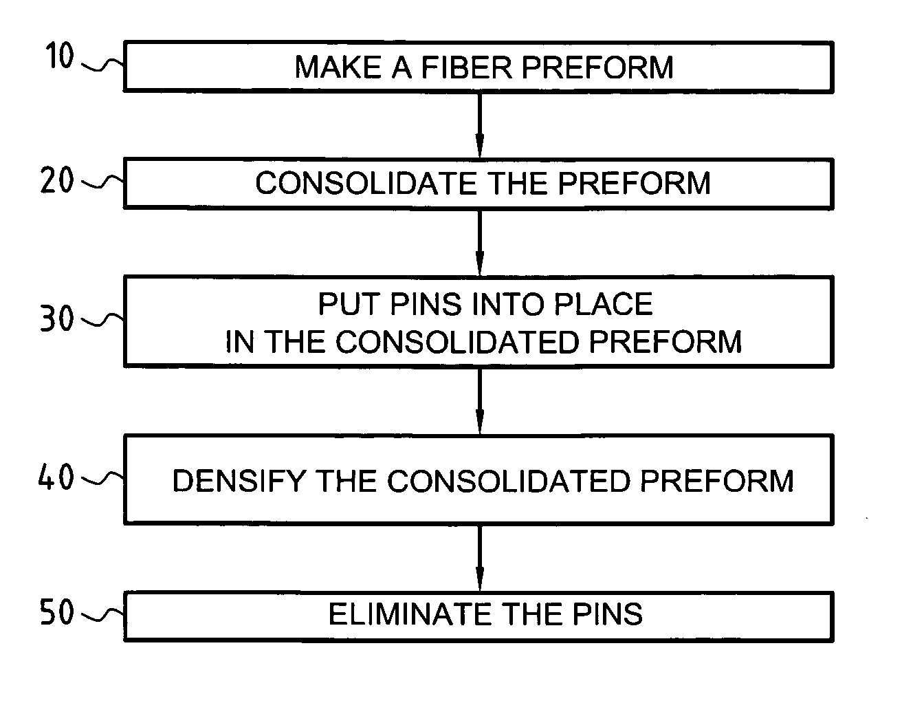
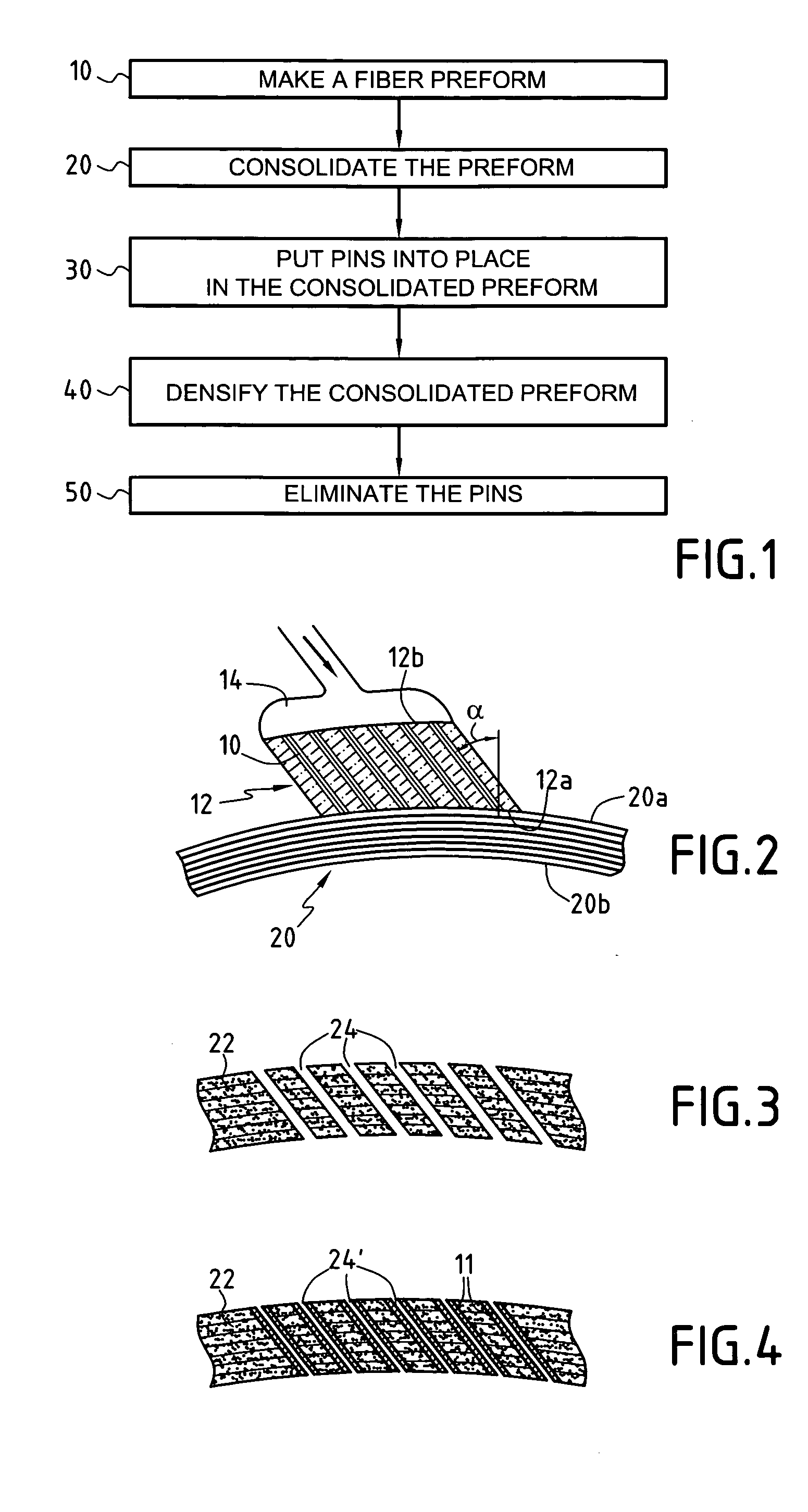
[0064] A fiber preform was made by multilayer weaving of SiC fiber yarns supplied under the reference "Hi-Nicalon" by the Japanese supplier Nippon Carbon, the preform comprising ten layers. The pore volume fraction of the preform was approximately equal to 65%.

[0065] The preform was consolidated by forming a PyC interphase and depositing SiC by chemical vapor infiltration, with the pore volume fraction being reduced to a value of about 55%.

[0066] After consolidation, pins having a diameter of 0.3 mm were put into place, the pins being made of carbon yarns stiffened by being impregnated with a BMI resin. The pins were put into place normally to the multilayer fiber fabric, and they were of a length such as to project from both sides of the preform.

[0067] The preform was subsequently densified by a self-healing ceramic matrix of the Si--B--C type, as described in U.S. Pat. No. 5,246,736.

[0068] After densification, the projecting ends of the pins were eroded so as to lay their carbon b...

example 2

[0070] A fiber preform was made by multilayer weaving of carbon fiber yarns, the preform comprising five layers. The volume fraction of the pores of the preform was approximately equal to 60%.

[0071] The preform was consolidated by depositing SiC by chemical vapor infiltration with the volume fraction of the pores being reduced to a value of about 50%.

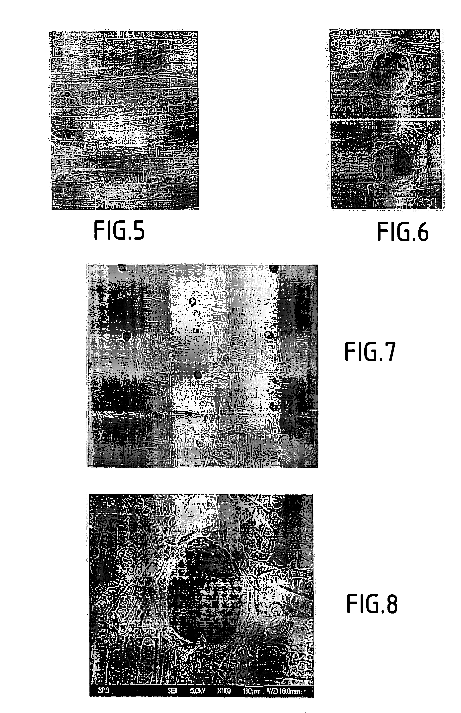
[0072] After consolidation, 0.3 mm diameter pins were put into place in the preform, the pins being formed by carbon yarns stiffened by being impregnated with a BMI resin. The pins were put implanted at an angle of 45.degree. relative to the normal at the surface of the preform. The pins were long enough to project from both sides of the preform.

[0073] The preform was densified and the pins were then eliminated as in Example 1. The resulting perforations are shown in the photographs of FIGS. 7 and 8.


PUM

PropertyMeasurementUnit
diameteraaaaaaaaaa
pressureaaaaaaaaaa
temperatureaaaaaaaaaa

Abstract

A fiber preform for constituting the fiber reinforcement of composite material is prepared and then consolidated by depositing sufficient matrix phase therein to bond the fibers together while not completely densifying the preform. Pins of rigid material are put into place through the consolidated preform and densification of the consolidated preform containing the pins is continued by depositing at least a ceramic matrix phase. Thereafter, at least a portion of each pin is eliminated so as to leave a calibrated perforation passing through the resulting part, the pins being made at least in part out of a material that can be eliminated by applying treatment that does not affect the ceramic material of the matrix.

Description

[0001] The invention relates to making a multi-perforated part out of ceramic matrix composite material. A particular field of application of the invention is making combustion chamber walls for gas turbines, in particular for airplane jets, which walls are provided with a plurality of perforations enabling them to be cooled by a flow of air.[0002] Ceramic matrix composite (CMC) materials are thermostructural materials, i.e. materials having good mechanical properties and the ability to retain them at high temperature. They comprise fiber reinforcement made of refractory fibers (generally carbon fibers or ceramic fibers) and they are densified by a ceramic matrix or by a combined carbon and ceramic matrix. An interphase layer, e.g. of pyrolytic carbon (PyC) or of boron nitride (BN) can be interposed between the reinforcing fibers and the ceramic matrix in order to improve the mechanical behavior of the material.[0003] Making a part out of CMC normally comprises preparing a fiber pre...

Claims


Application Information

Patent Timeline
Patent Type & Authority Applications(United States)
IPC IPC(8): B28B1/44F02C7/00B28B7/34C04B35/565C04B35/80C04B38/00F23R3/00F23R3/42
CPCB28B1/44B28B7/342C04B35/565C04B35/62863C04B35/62873C04B35/62884C04B35/806C04B38/0003C04B2235/5244C04B2235/5248F23M2900/05004F23R3/007F23R2900/00018Y02T50/67C04B35/52C04B38/068C04B35/83C04B35/80Y02T50/60
Inventor BOUILLON, ERICCOUPE, DOMINIQUEBOUVIER, REMI
Owner SN DETUDE & DE CONSTR DE MOTEURS DAVIATION S N E C M A
Why Eureka
Try Eureka