Shielded energy conditioner
a technology of energy conditioner and shielding, which is applied in the direction of fixed capacitor details, feed-through capacitors, line-transmission details, etc., to achieve the effect of reducing the effect of line voltage and rapid change of load
- Summary
- Abstract
- Description
- Claims
- Application Information
AI Technical Summary
Benefits of technology
Problems solved by technology
Method used
Image
Examples
second embodiment
[0165] FIG. 15 illustrates the invention including more than one plate forming each one of the first electrode and the second electrode.
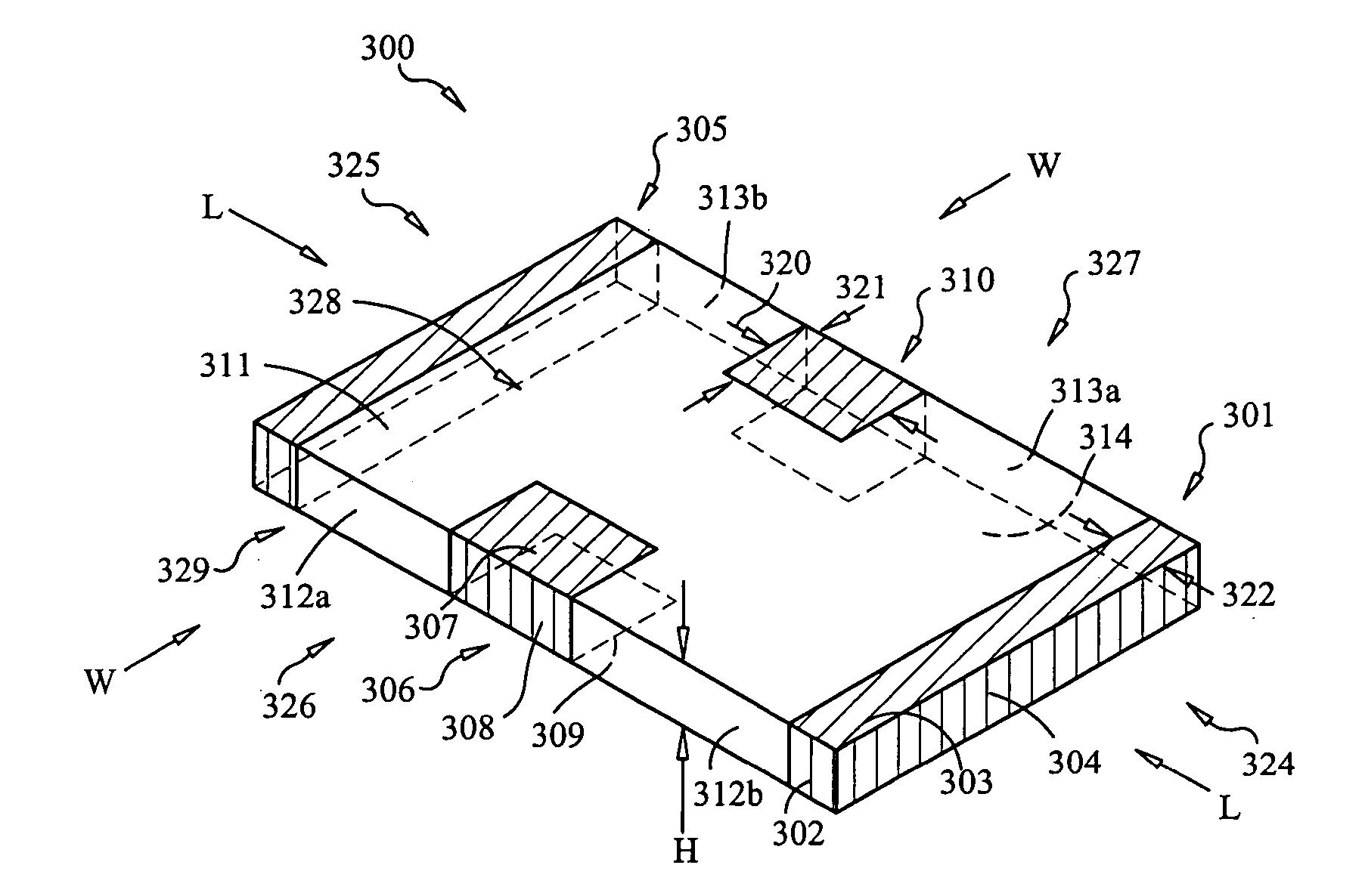
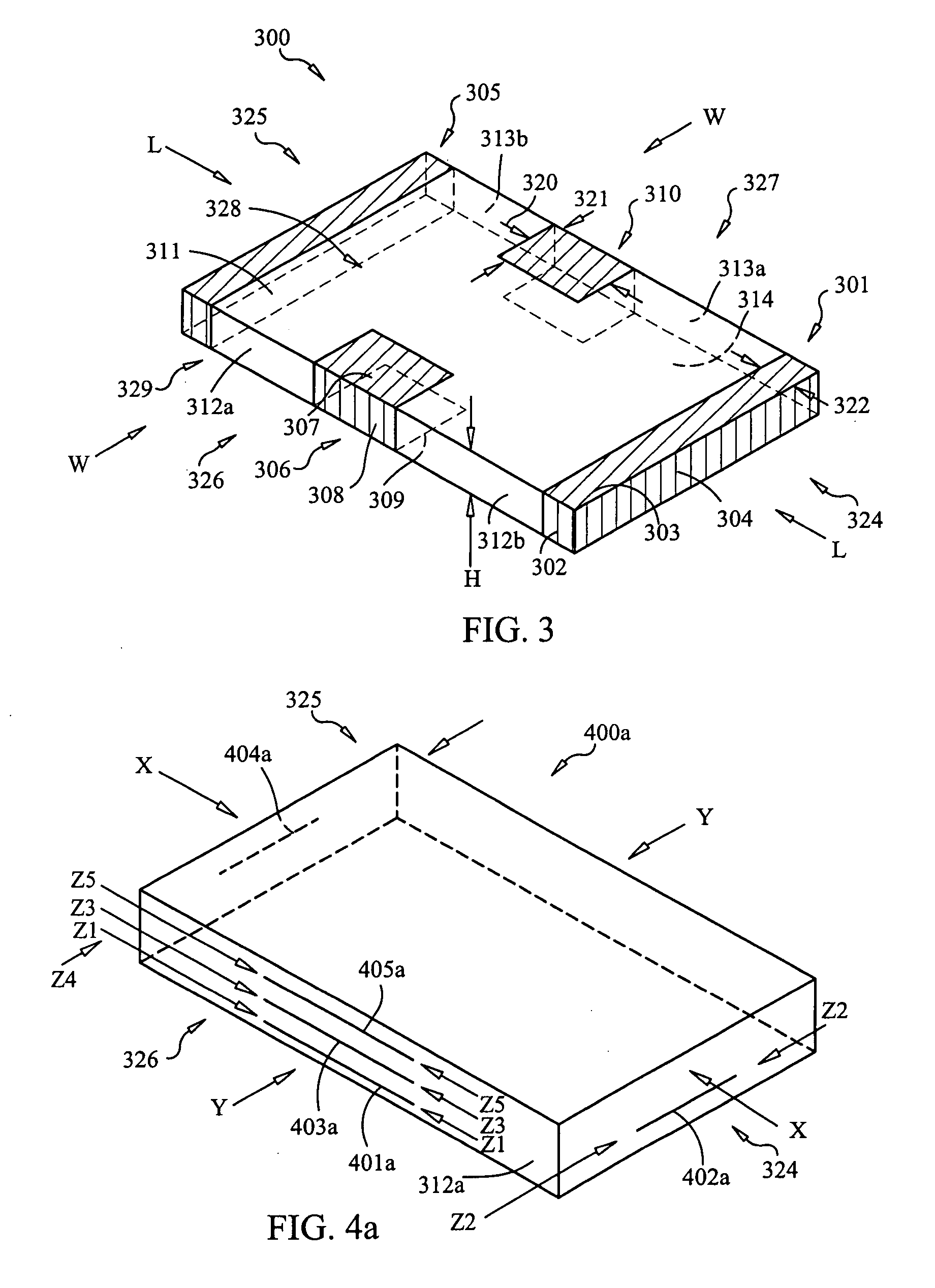
[0166] FIG. 15 illustrates another novel device structure 1500 having the outer surface structure shown in FIG. 3. Structure 1500 includes shielding electrode bottom plate 1501; shielding electrode middle plates 1503, 1505, 1507, 1509, 1511, 1513, 1515, 1517, 1519; shielding electrode top plate 1521; first electrode lower plate 1502; first electrode middle plates 1506, 1510, 1514; first electrode upper plate 1518; second electrode lower plate 1504; second electrode plates 1504, 1508, 1512, 1516; and second electrode upper plate 1518. Structure 1500 also includes edge interconnection structure in the form of side electrode terminal 301 defining side electrode terminal conductive portion 1571 in top surface 328 and side electrode terminal side portion 1522 in side surface 324.
[0167] Structure 1500 includes 11 shield plates for the shielding electrode ...
fourth embodiment
[0178] In a fourth alternative embodiment indicated by dashed line 1670, at least one of and preferably all of the shield electrode plates have a shield electrode plate extension, like shielding electrode plate extension 1670 of shielding electrode plate 1601, indicated by the dashed line in FIG. 16a, that extends away from the region of overlapped plates and / or the region between wire lines 1610, 1611 beyond wire line 1640, preferably also extends beyond the extension of at least one of the extension regions 1620, 1621 of the plates of the first electrode, and preferably extends beyond the extension of all of the extension regions of the first and second electrodes. In this fourth embodiment, plate 1601 includes aperture 1680 in which a section of wire line 1610 resides. Aperture 1680 is large enough to prevents electrical contact of wire line 1610 to shielding electrode plate 1601.
[0179] In another and fifth alternative embodiment relating to FIG. 16a, conductive wire line 1690, i...
sixth embodiment
[0184] In a six alternative embodiment, plate 1602 includes one or more apertures 1691 away from the periphery of electrode plate 1602. In the sixth embodiment, non-peripheral wire lines extend through apertures 1602 such that the non-peripheral wire lines do not electrically connect to electrode plate 1602, and each such non-peripheral wire does electrically connect to at least on other plate in structure 1600. For example, non-peripheral wire lines may connect all plates of one electrode to one another, may connect all plates of each non-shielding electrode to one another, or may connect all plates of the shielding electrode to one another.
[0185] FIG. 17 shows in plan view visible sections of a stack consisting of first electrode plate 1701 and second electrode plate 1720 for purposes of illustrating examples of energy pathway line segments and energy perpendicular line segments.
[0186] FIG. 17 shows plate stack 1700 including top plate 1701 and bottom plate 1720. Top plate 1701 in...
PUM
 Abstract
Description
Claims
Application Information
 - R&D
- Intellectual Property
- Life Sciences
- Materials
- Tech Scout
- Unparalleled Data Quality
- Higher Quality Content
- 60% Fewer Hallucinations
Browse by: Latest US Patents, China's latest patents, Technical Efficacy Thesaurus, Application Domain, Technology Topic, Popular Technical Reports.
© 2025 PatSnap. All rights reserved.Legal|Privacy policy|Modern Slavery Act Transparency Statement|Sitemap|About US| Contact US: help@patsnap.com


