
Accelerated artificial weathering test systems

a test system and artificial weathering technology, applied in material thermal analysis, radiation therapy, material testing goods, etc., can solve the problems of negative test effect, low emissivity, complex double cooling system,

Inactive Publication Date: 2004-11-25
SEVAR SOC DES ENCEINTES DE VIEILLISSEMENT
View PDF22 Cites 25 Cited by
  • Summary
  • Abstract
  • Description
  • Claims
  • Application Information

AI Technical Summary

Benefits of technology

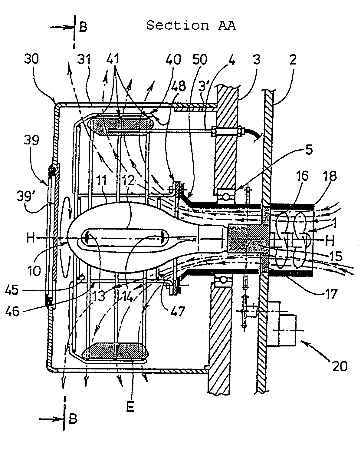
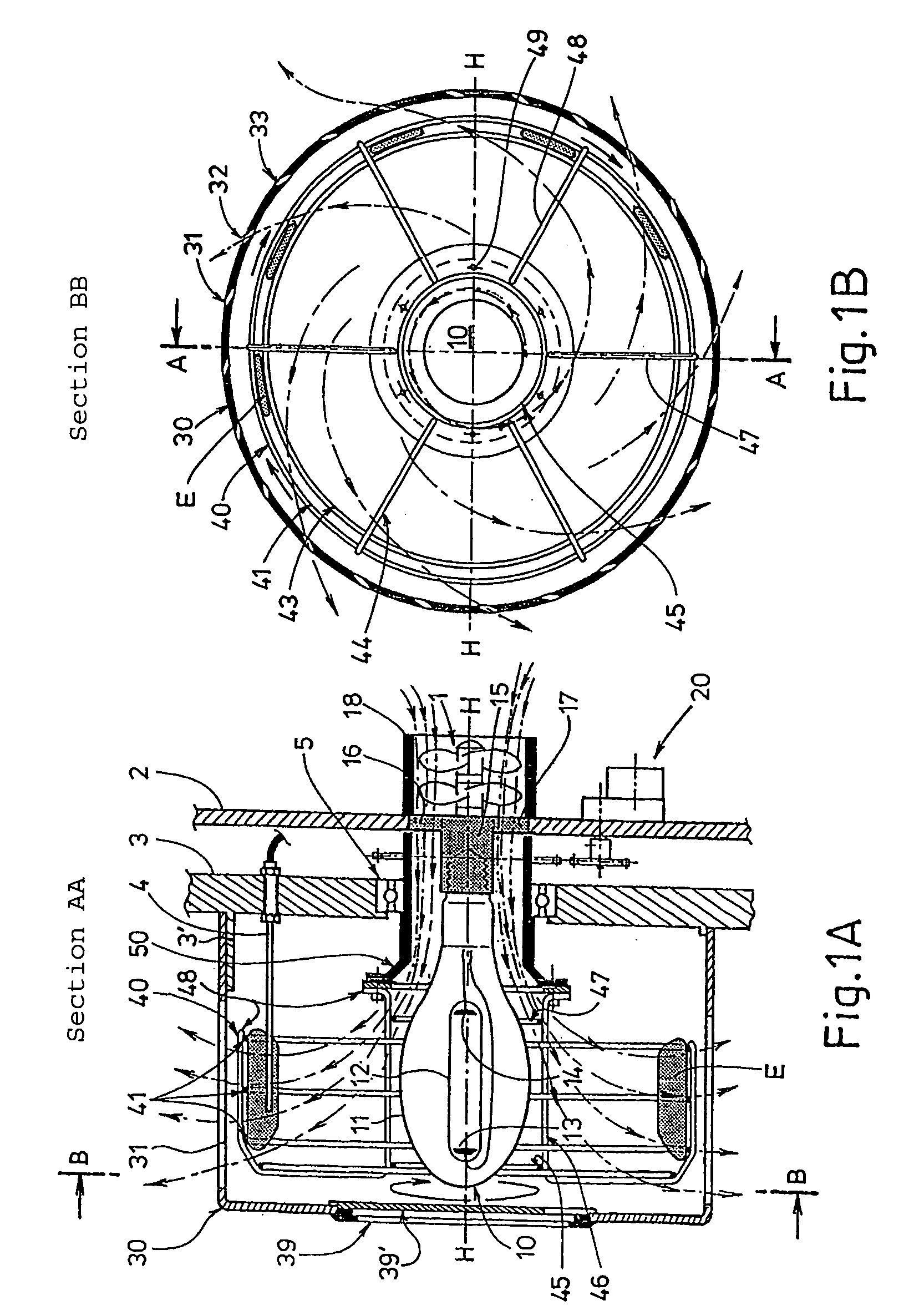
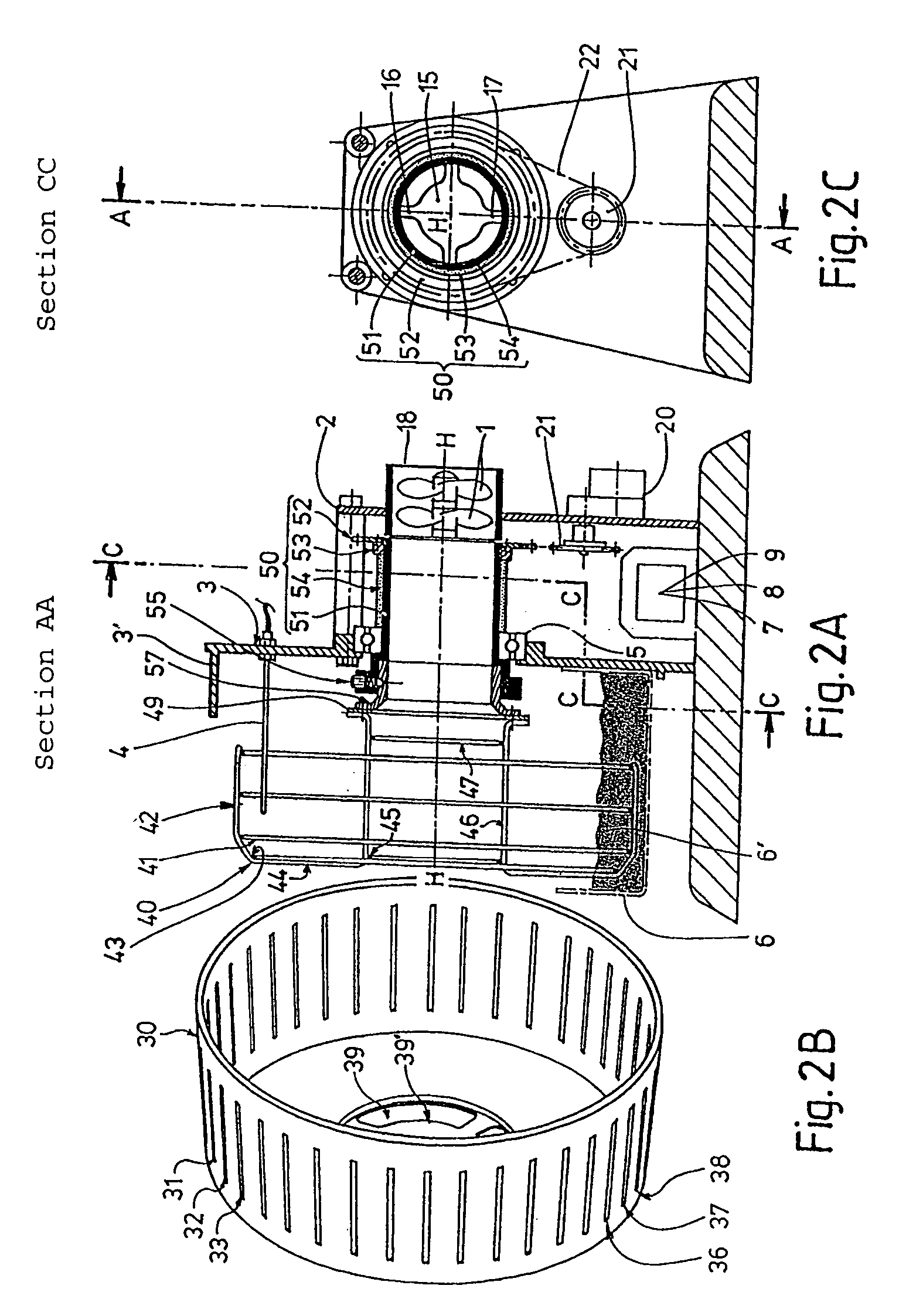
[0060] the improvement being that the ventilation means blow air into the chamber through the orifice that forms an air intake orifice arranged approximately parallel to the horizontal axis, the lamp being placed along the immediate axial prolongation of the air intake orifice, so as to generate an air stream arriving directly on the lamp and approximately parallel to the axis along the central part of the cage, the air stream diverging around the lamp and being evacuated approximately perpendicular to the axis through fixed openings that form air openings around the periphery of the cage, such that the temperature of the air stream increases as it comes into contact with the lamp, before going around the samples, thus increasing their temperature and then keeping the temperature uniform.
[0105] Subsequently, it is possible to regulate the temperature of the air stream by slaving the lamp electrical power supply and / or the air stream generation means to the temperature.

Problems solved by technology

Due to the large release of heat, carbon arc lamp devices have a complex double cooling system, firstly to cool the burner, and secondly to cool the samples.
The disadvantage of the radiation from low-pressure arc tubes is that emissivity is low and the ultraviolet spectrum is very different from the solar spectrum, which has a negative effect on the tests.
Another disadvantage is that samples cannot be exposed uniformly in these devices, such that the reproducibility of test results is not good.
However, these lamps release a great deal of heat and open circuit or closed circuit air circulation is necessary to keep the samples at a controlled temperature.
These apparatuses have the disadvantage that they expose the samples to variable temperatures.
Therefore, identical samples at different heights are subjected to different temperatures, and this also affects the reproducibility of the tests.
One disadvantage of this device is that it is excessively large compared with the small area of the samples being tested.
This device also has the disadvantage that it has large light energy losses, since more than 75% of the light does not travel directly towards the sample holder.
Consequently, the efficiency of this device per unit area of samples being tested is low, when the depreciation of the equipment plus energy expenses are included, making the tests expensive.
However despite the laminar air stream, this instrument still has the disadvantage that it exposes the samples to different temperatures, the laminar air stream becoming warmed further as it comes into contact with samples exposed to bright light radiation.
This vertical low flow rate laminar air stream test cabinet has the disadvantage that it does not provide efficient cooling of the samples and it induces temperature differences between samples at the bottom and samples at the top of the rack.
The disadvantage of this device is the complexity and the particularly large size of its double flow air circulation system.
Another disadvantage with this device is that its testing space and the number of samples that it can hold are very limited, considering the large size of the cabinet including its equipment for evacuation of air near the top, the blower and the rotation drive near the bottom, and the peripheral air circulation system and the lateral cooling air source.
This double air stream cooling system has another disadvantage, which is that it induces significant temperature differences between the irradiated inner face and the cooled outer face of the samples.
In this device, the light tubes and a sprinkler system are arranged in the ducts that separate them from the samples, but this has the disadvantage that it hinders light exposure of the samples and reduces the efficiency of the system.
Another disadvantage of this device is that the vertical air stream that passes through the sample-holding drum does not cool the samples efficiently.
Devices according to the state of the art using Xenon arc lamps or Carbon arc torches have a low efficiency, which requires a high electrical power and large capacity cooling equipment that invariably causes instability and large variations in the temperature of the samples during the test.

Method used


Image

  • Accelerated artificial weathering test systems
  • Accelerated artificial weathering test systems
  • Accelerated artificial weathering test systems

Examples


Embodiment Construction

[0249] Thus, according to the optimum embodiment of the invention illustrated in FIGS. 7A and 7B, a tank 60 (in other words a basin or a reservoir) that will contain a liquid 61, particularly water or various aqueous compositions, is arranged on the inside of the chamber 30 such that the sample-holding cage 40 is partially immersed in the liquid 61 contained in the tank 60.

[0250] The tank 60 is rigidly fixed to the ring plate 3 of the partition in the lower part of the chamber.

[0251] The tank 60 is preferably a crescent-shaped basin to match the cylindrical chamber 30 and cage 40. Other shapes could be adopted depending on the shape of the chamber.

[0252] The width and the vertical depth of the tank 60 are sufficiently large so that they surround a fairly large portion of the cage 40.

[0253] Typically, the useful height H of the tank is of the order of one third of the radial dimension R of the cage, but the useful height H can reach higher values, up to the value of the radius R of t...


PUM

PropertyMeasurementUnit
temperatureaaaaaaaaaa
poweraaaaaaaaaa
sizeaaaaaaaaaa

Abstract

The invention concerns a device for exposing samples to photonic radiation for accelerated artificial weathering tests, comprising: a chamber (30), a sample-holding cage (40) rotating about a horizontal axis (H-H), at least an electromagnetic radiation lamp (10) in the central part of the cage (45, 46). One improvement consists in ventilating means blowing air into the chamber (30) through the air intake orifice (50), so as to generate an air stream arriving directly on the lamp (10), then diverging about the lamp (10) to be cvacuated through the fixed air outlets (31-38) at the periphery of the cage (40). Another improvement consists in the fact that the lower part of the rotary sample-holding cage is immersed in a liquid tank, such that the samples are cyclically in immersion phases into the liquid alternating with emergence phases into the air stream. The invention also concerns test devices and methods integrating said improvements.

Description

BACKGROUND OF INVENTION[0001] 1. Technical field[0002] This invention relates to the field of electromagnetic radiation source devices and apparatuses for testing accelerated weathering of samples under the effect of light, and other atmospheric conditions such as temperature, humidity or water precipitation. In particular, the tests relate to the resistance of samples made of polymer materials that are essentially sensitive to ultraviolet radiation.[0003] 2. State of prior art[0004] Natural weathering of materials under solar light is simulated in a known manner by exposing samples to an electromagnetic radiation source with a spectral distribution that must be carefully chosen to achieve accelerated weathering that can be correlated to weathering observed under natural conditions.[0005] Various devices and apparatuses are known for controlling exposure to laboratory light sources. The nature of light radiation sources has an overriding influence on test conditions and fully determ...

Claims


Application Information

Patent Timeline
Patent Type & Authority Applications(United States)
IPC IPC(8): G01N17/00G01N33/44
CPCG01N17/004G01N33/442
Inventor BERAUD, MICHEL PIERRE PAUL
Owner SEVAR SOC DES ENCEINTES DE VIEILLISSEMENT
Learn More