Method and apparatus for obtaining a micro sample downhole

a micro-sample and sampling technology, applied in the field of downhole sampling analysis, can solve the problems of reducing the ability to evaluate the actual properties of the formation fluid, wasting time and resources, and requiring weeks or months to receive a full laboratory analysis of the sampl

Inactive Publication Date: 2004-12-09
BAKER HUGHES INC
View PDF14 Cites 41 Cited by
  • Summary
  • Abstract
  • Description
  • Claims
  • Application Information

AI Technical Summary

Benefits of technology

[0008] Temperatures downhole in a deep wellbore often exceed 300 degrees F. When a hot formation fluid sample is retrieved to the surface at 70 degrees F., the resulting drop in temperature causes the formation fluid sample to contract. If the volume of the sample is unchanged, such contraction substantially reduces the sample pressure. A pressure drop causes changes in the situ formation fluid parameters, and can permit phase separation between liquids and gases entrained within the formation fluid sample. Phase separation significantly changes the formation fluid characteristics, and reduces the ability to evaluate the actual properties of the formation fluid.
[0010] Typically, sample tanks are transported to laboratories for analysis for determination of formation fluid properties based on the sample. The samples typically have to be transferred to a transportation tank, thus risking sample damage and spoilage due to pressure loss and formation of bubbles or asphaltene precipitation within the sample. Moreover, even if the sample is transferred successfully to the laboratory, it typically takes weeks or months to receive a full laboratory analysis of the sample. Thus there is a need for a rapid sample analysis system that provides accurate results and eliminates the risk of sample spoilage.
[0011] The present invention addresses the shortcomings of the related art described above. The present invention provides a downhole sample tank and a plurality of micro sample chambers. The micro sample chambers can have at least one window for introduction of visible, near-infrared (NIR), mid-infrared (MIR) and other electromagnetic energy into the tank for samples collected in the micro sample chamber downhole from an earth boring or well bore. The window is made of sapphire or another material capable of allowing electromagnetic energy to pass through the window. The entire micro sample chamber can be made of sapphire or another material capable of allowing electromagnetic energy to pass another material enabling visual inspection or analysis of the sample inside the micro sample chamber. The micro sample chamber enables immediate testing of the sample on location at the surface to determine the quality of the sample in the main sample tank or to enable comprehensive testing of the sample.

Problems solved by technology

Phase separation significantly changes the formation fluid characteristics, and reduces the ability to evaluate the actual properties of the formation fluid.
The samples typically have to be transferred to a transportation tank, thus risking sample damage and spoilage due to pressure loss and formation of bubbles or asphaltene precipitation within the sample.
Moreover, even if the sample is transferred successfully to the laboratory, it typically takes weeks or months to receive a full laboratory analysis of the sample.

Method used


Image

  • Method and apparatus for obtaining a micro sample downhole
  • Method and apparatus for obtaining a micro sample downhole
  • Method and apparatus for obtaining a micro sample downhole

Examples


Embodiment Construction

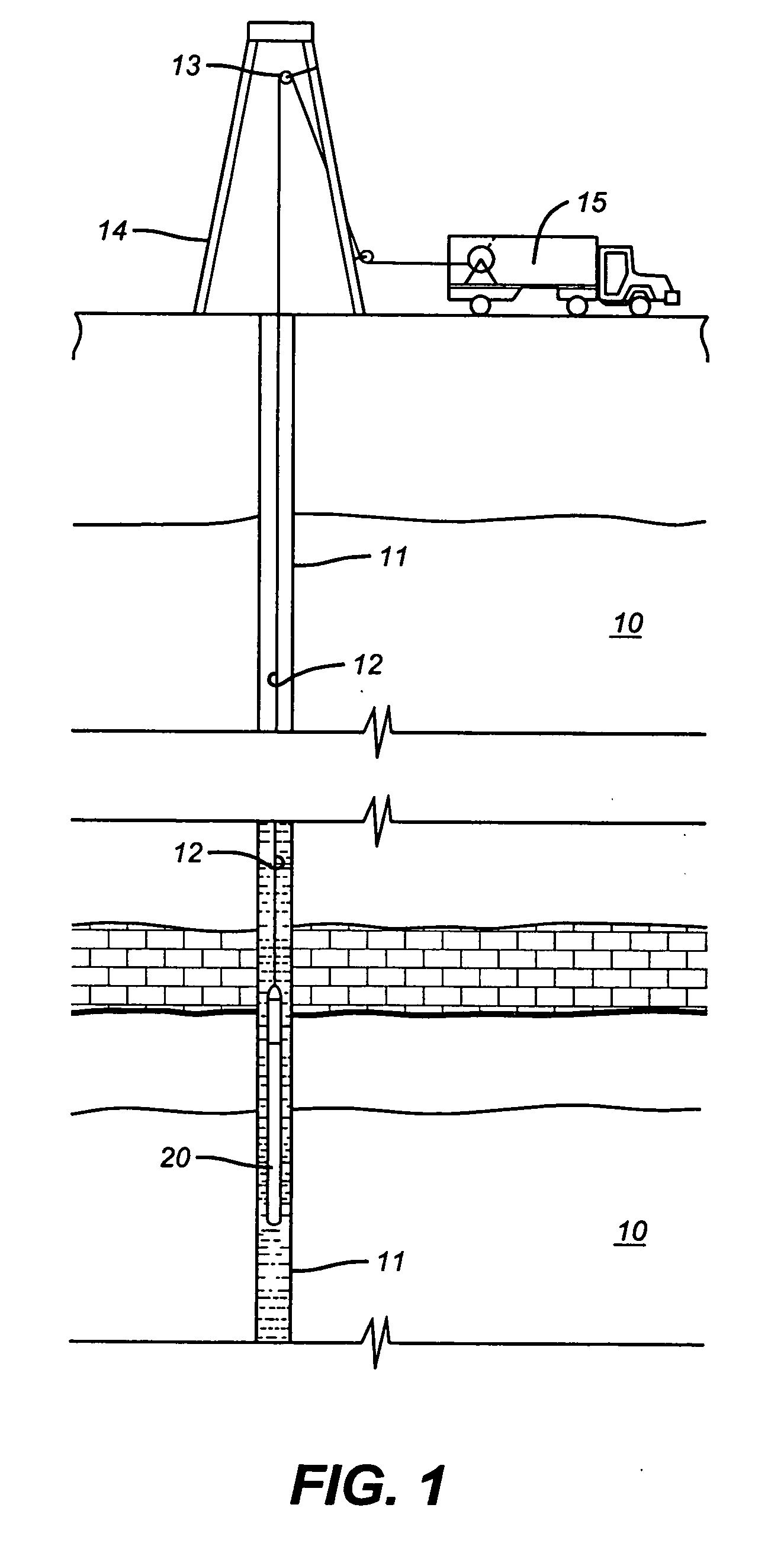
[0022] FIG. 1 schematically represents a cross-section of earth 10 along the length of a wellbore penetration 11. Usually, the wellbore will be at least partially filled with a mixture of liquids including water, drilling fluid, and formation fluids that are indigenous to the earth formations penetrated by the wellbore. Hereinafter, such fluid mixtures are referred to as "wellbore fluids". The term "formation fluid" hereinafter refers to a specific formation fluid exclusive of any substantial mixture or contamination by fluids not naturally present in the specific formation.

[0023] Suspended within the wellbore 11 at the bottom end of a wireline 12 is a formation fluid sampling tool 20. The wireline 12 is often carried over a pulley 13 supported by a derrick 14. Wireline deployment and retrieval is performed by a powered winch carried by a service truck 15, for example.

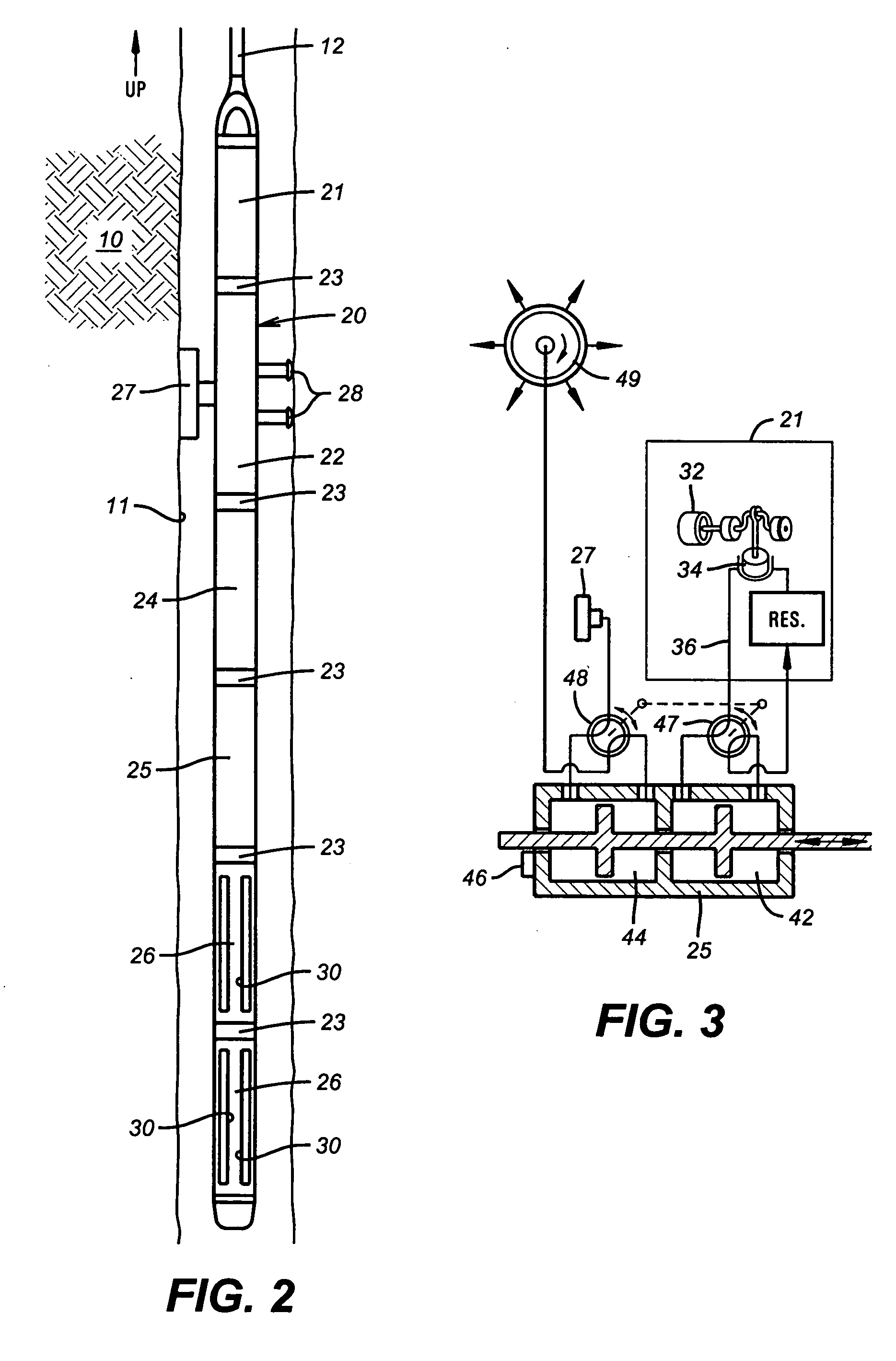
[0024] Pursuant to the present invention, an exemplary embodiment of a sampling tool 20 is schematically illustrated...


PUM

PropertyMeasurementUnit
electromagnetic energyaaaaaaaaaa
optical analysisaaaaaaaaaa
pressureaaaaaaaaaa

Abstract

The present invention provides a downhole sample tank and a plurality of micro sample chambers. The micro sample chambers can have at least one window for introduction of visible, near-infrared (NIR), mid-infrared (MIR) and other electromagnetic energy into the tank for samples collected in the micro sample chamber downhole from an earth boring or well bore. The window is made of sapphire or another material capable of allowing electromagnetic energy to pass through the window. The entire micro sample chamber can be made of sapphire or another material capable of allowing electromagnetic energy to pass another material enabling visual inspection or analysis of the sample inside the micro sample chamber. The micro sample chamber enables immediate testing of the sample on location at the surface to determine the quality of the sample in the main sample tank or to enable comprehensive testing of the sample.

Description

[0001] This patent application claims priority from U.S. Provisional Patent Application Ser. No. 60 / 467,668 entitled "A Method and Apparatus for an Advanced Optical Cylinder" by M. Shammai et al. filed on May 2, 2003.[0002] 1. Field of the Invention[0003] The present invention relates generally to the field of downhole sampling analysis and in particular to obtaining an aliquot formation fluid micro sample down hole for rapid analysis on location to determine the quality of the down hole sample.[0004] 2. Summary of the Related Art[0005] Earth formation fluids in a hydrocarbon producing well typically comprise a mixture of oil, gas, and water. The pressure, temperature and volume of formation fluids control the phase relation of these constituents. In a subsurface formation, high well fluid pressures often entrain gas within the oil above the bubble point pressure. When the pressure is reduced, the entrained or dissolved gaseous compounds separate from the liquid phase sample. The ac...

Claims


Application Information

Patent Timeline
Patent Type & Authority Applications(United States)
IPC IPC(8): E21B49/08G01N1/14G01N21/31G01N21/65G01N33/28G01V8/02
CPCE21B49/081G01N1/14G01N21/31G01N21/65G01N33/2823G01N2021/651G01V8/02
Inventor SHAMMAI, MICHAELGORDON, ROBERTSANCHEZ, FRANCISCO GALVAN
Owner BAKER HUGHES INC
Why Eureka
Try Eureka