However, in the region of low concentration of carbon, the decarburization rate falls, so a long time is required until reaching the desired concentration of carbon.
Further, to raise the ratio of the
inert gas in the blown gas, the amount of consumption of the expensive
inert gas greatly increases.
This is also not advantageous economically.
On the other hand, it is extremely difficult to refine ultra-low carbon chromium steel with a concentration of carbon of not more than 0.01% by the AOD method.
Therefore this cannot be said to be an efficient decarburization refining method.
Therefore, compared with usual refining of low carbon chromium steel, a drop in productivity of the decarburization refining is invited and an increase in the refining costs is caused.
The amount of this generated increases sharply when the degree of vacuum rises (when a high vacuum is reached) and deposits on the
alloy addition port, furnace cover, ducts, etc. at the top of the refining vessel to block the same or cause trouble in various equipment and operations and obstruct productivity.
This will also become major trouble in the equipment and worsen the productivity.
Among these, the oxygen blow rate can be controlled to a certain extent by the flow adjustment valve of the oxygen gas, but no sufficient control method has been established for the degree of vacuum.
In the above prior art, when using ejectors, the method of successively starting and stopping a large number of ejectors does not allow extremely fine control of the degree of vacuum since the ranges of capacity of the ejectors themselves are broad.
Further, as seen in Japanese Unexamined Patent Publication (Kokai) No. 10-1716, the method of allowing gas to leak in from the outside while operating the exhaust unit (for example, using
nitrogen) enables control of the degree of vacuum to a certain extent, but has the defect that the gas costs rise.
However, while control of the degree of vacuum itself is possible, the
exhaust gas sucked in contains a
high concentration of CO gas, so when mixing in air containing a
combustion-assisting gas constituted by oxygen, there is the danger of
combustion and explosion.
Employment for actual machinery is extremely dangerous.
Further, if allowing gas to leak in from the outside, the load on the exhaust unit increases.
Further, the method of controlling the amount of supply of steam to an ejector used in this patent relies on the fact that the optimum steam flow rate of an ejector is distinctive, so changing this remarkably reduces the exhaust performance of the ejector itself.
Further, at the same time, a slight fluctuation in the amount of steam is overly sensitively reflected in the ejector performance, so extremely fine control of the pressure inside the refining vessel becomes difficult.
On the other hand, the method of using a water-sealed type
vacuum pump is currently employed for control of the degree of vacuum by pump units, but this is not used together with ejectors, the capacity is insufficient for realizing a high vacuum by this alone, and extremely fine control of the degree of vacuum is impossible.
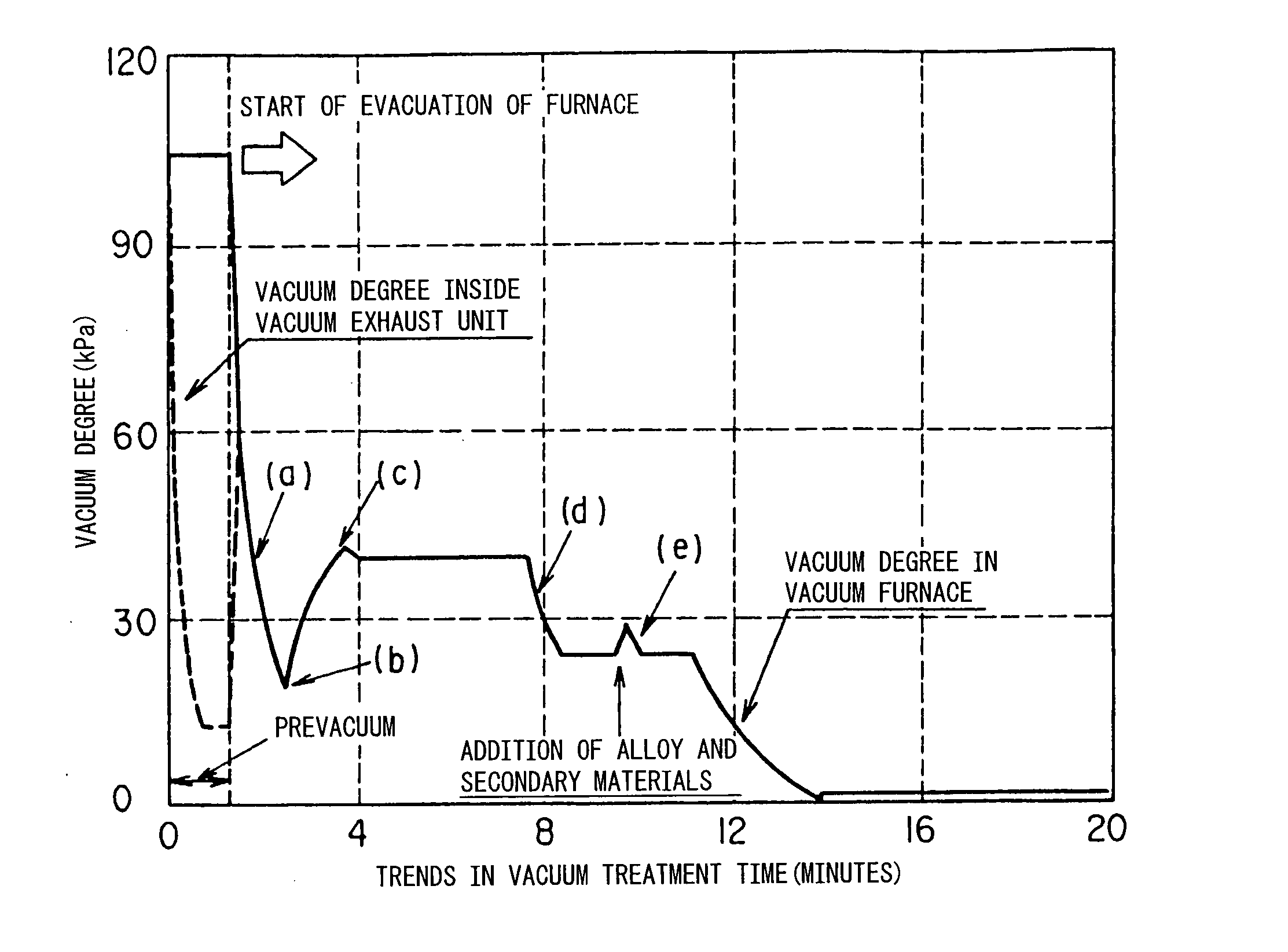
However, due to the
argon blown into the refining vessel for agitating the melt or the oxygen blown for promoting decarburization, splash of the
metal and
slag, generation of dust, etc. occur inside the refining vessel.
Therefore, the
metal deposits at the
alloy and secondary material addition port linked with the inside of the vessel and accordingly the addition port becomes blocked or other trouble easily occurs.
If considering continuous long term operation of a vacuum refining vessel, however, neither means is sufficient in practice.
Due to abrasion and reduced thickness of the
piping and ducts,
cracking due to thermal stress, etc., sometimes the cooling water leaks from the
piping and ducts to the inside of the
exhaust gas passage.
Exhaust gas treatment equipment is generally closed, however, so it is impossible to obtain a grasp of the state of
water leakage inside.
Therefore, sometimes operation is continued while not being able to confirm internal
water leakage and the
water leakage becomes serious and leads to a remarkable drop in the degree of vacuum or the inability to remove dust from the
system due to the water leakage or other trouble in equipment or operation.
If stopping operation and conducting checks on a scheduled basis, however, the operating efficiency of the facilities will be reduced and the productivity blocked.
On the other hand, with the above-mentioned electrostatic capacity type detection rod, it is difficult to adjust the electrostatic capacity of the detection rod according to the state of wetness of the dust.
For example, with a small amount of water leakage, if the temperature is high or under a vacuum, the water will easily turn into steam, so detection of water leakage will not be possible.
Therefore, it is extremely difficult to detect water leakage in advance while still slight.
Steel seal pots have a good closeability, but suffer from the problems of
corrosion and swelling capital costs.
On the other hand, concrete hot wells are free from
corrosion and relatively inexpensive in terms of capital costs as well, but suffer from problems in the sealability with the top steel covers.
The first is that there is leakage of CO-containing gas from a hot well.
However, the inside of a hot well being made negative pressure due to suction of gas means suction of air from the seal parts.
If the suction fan were to stop in this state for some reason or another, a large amount of CO-containing gas would leak from the expanded clearance of the seal parts.
This being so, the cooling water in the hot well will continue to increase and will overflow.
As a measure against this, it may be considered to attach a switch valve from another power
source system to the supply
pipe to the condenser and water-sealed pump, but tremendous expense would become required for the long distance pipeline and the large switching valve.

