

Condensing lens, optically-multiplexed-laser-light source, and exposure system
a technology of lens, which is applied in the field of condensing lens and optical multi-laser light source, and exposure system, can solve the problems of large size of excimer laser, high manufacturing and maintenance cost of excimer laser, and low wavelength conversion efficiency
- Summary
- Abstract
- Description
- Claims
- Application Information
AI Technical Summary
Benefits of technology
Problems solved by technology
Method used
Image

Examples
first embodiment
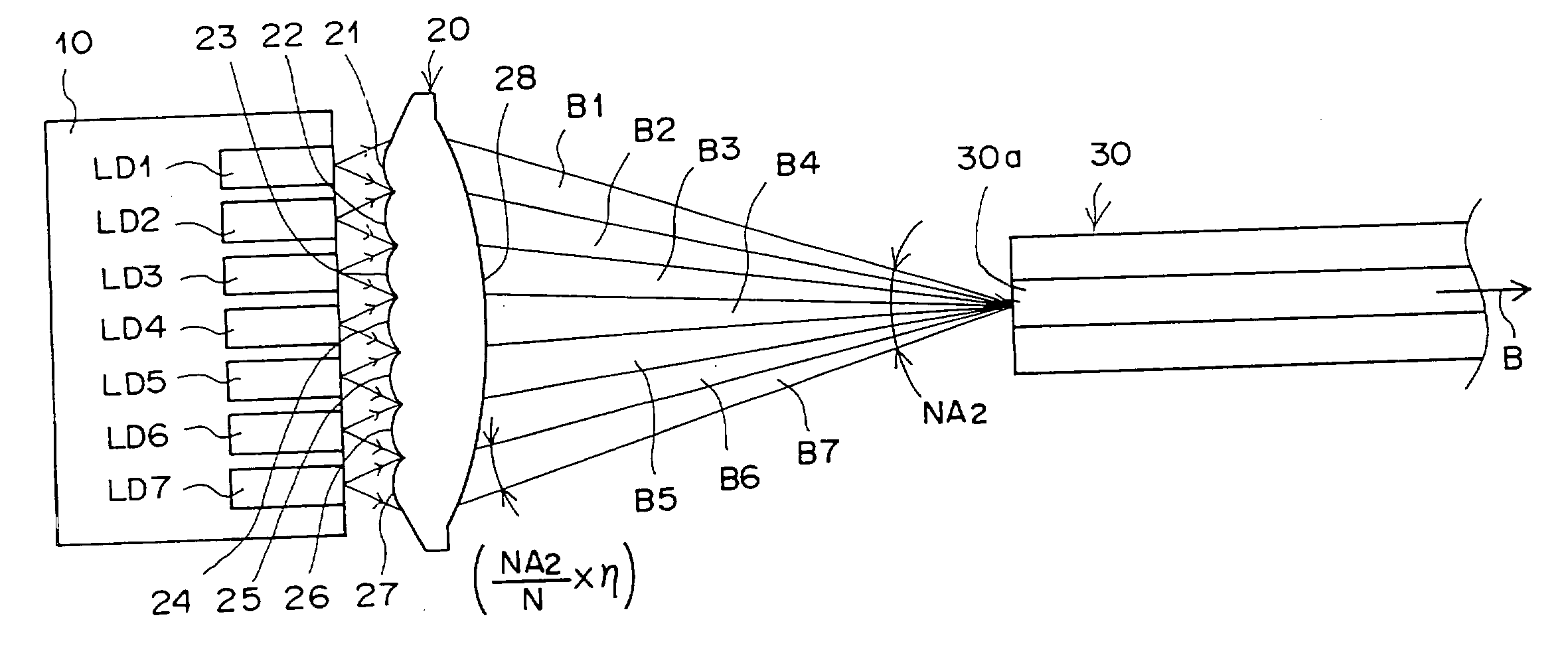
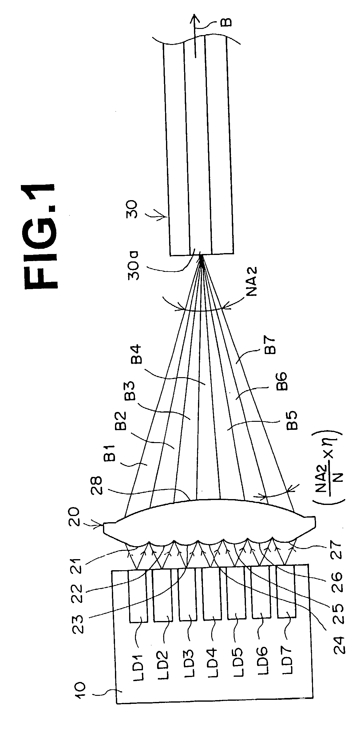
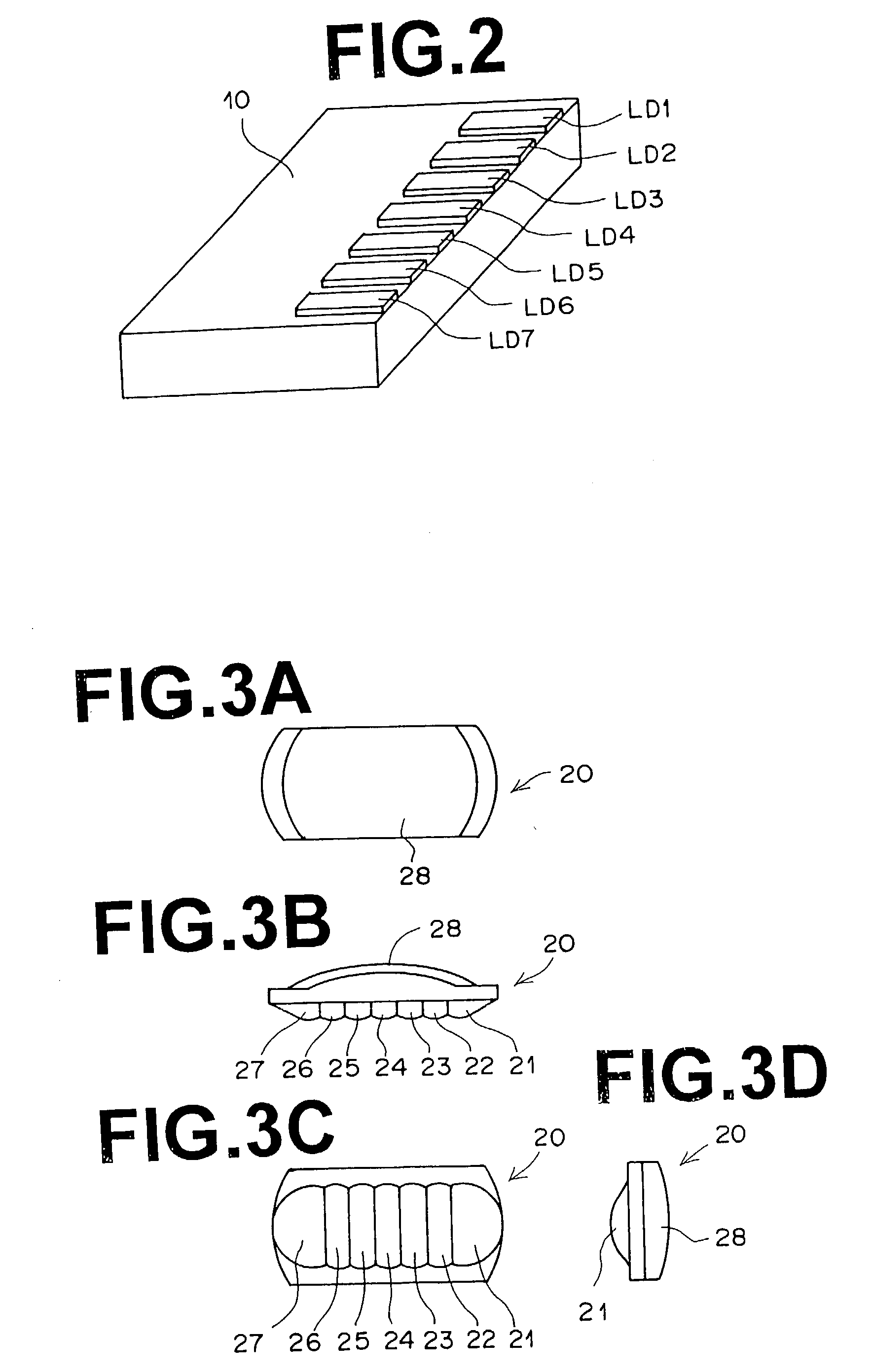
[0080] FIG. 1 is a plan view of an optically-multiplexed-laser-light source comprising a condensing lens 20 according to the present invention. As illustrated in FIG. 1, the optically multiplexed-laser-light source of FIG. 1 comprises GaN-based semiconductor laser chips LD1 through LD7, the condensing lens 20, and a multimode optical fiber 30. Each of the GaN-based semiconductor laser chips LD1 through LD7 operates in multiple transverse modes, and the number of the GaN-based semiconductor laser chips LD1 through LD7 is seven in the example of FIG. 1. The GaN-based semiconductor laser chips LD1 through LD7 are arranged and fixed on a heat block 10 made of copper as shown in FIG. 2.
[0081] FIGS. 3A through 3D are front, bottom, back, and side views of the condensing lens 20 of the first embodiment, respectively. The seven collimator-lens portions 21 through 27 and the condensing lens portion 28 in the condensing lens 20 are integrally formed out of an identical material. For example, ...
second embodiment
[0104] Next, a condensing lens according to the second embodiment of the present invention will be explained below. FIGS. 8A, 8B, 8C, and 8D are front, bottom, back, and side views of a condensing lens 50 according to the second embodiment of the present invention, respectively. As illustrated in FIGS. 8A, 8B, 8C, and 8D, the condensing lens 50 comprises twelve collimator-lens portions arranged in two lens arrays and a single condensing lens portion 53, where the twelve collimator-lens portions and the condensing lens portion 53 in the condensing lens 50 are integrally formed out of an identical material. Each of the two lens arrays is constituted by two collimator-lens portions 51 being located on both ends of the lens array and each having a similar shape to each of the two collimator-lens portions 21 and 27 illustrated in FIGS. 3A to 3D and four collimator-lens portions 52 being located between the two collimator-lens portions 51 and each having a similar shape to each of the col...
third embodiment
[0106] Next, a condensing lens according to the third embodiment of the present invention will be explained below. FIGS. 9A, 9B, 9C, and 9D are front, bottom, back, and side views of a condensing lens 60 in the third embodiment of the present invention. As illustrated in FIGS. 9A, 9B, 9C, and 9D, the condensing lens 60 comprises eleven collimator-lens portions and a single condensing lens portion 63, where the eleven collimator-lens portions and the condensing lens portion 63 in the condensing lens 60 are integrally formed out of an identical material. Seven collimator-lens portions out of the eleven collimator-lens portions constitute a lens array which is constituted by two collimator-lens portions 61 being located on both ends of the lens array and each having a similar shape to each of the two collimator-lens portions 21 and 27 illustrated in FIGS. 3A to 3D and five collimator-lens portions 62 being located between the two collimator-lens portions 61 and each having a similar sh...
PUM
 Abstract
Description
Claims
Application Information