Method and apparatus for achieving worldwide reduction of carbon dioxide emissions and deforestation

a carbon dioxide and deforestation technology, applied in the field of methods and apparatuses for achieving worldwide reduction of carbon dioxide emissions and deforestation, can solve the problems of poor cooking performance of hot box solar cookers according to the state-of-the-art, large angle of beam radiation incidence, and failure of pv cell modules for electricity generation to disclose or suggest a combination of pv cells and solar cookers. , to achieve the effect of improving heat conductivity, reducing the coefficient o

Inactive Publication Date: 2004-12-09
ROMIJN MAARTEN MARTINUS
View PDF0 Cites 13 Cited by
  • Summary
  • Abstract
  • Description
  • Claims
  • Application Information

AI Technical Summary

Benefits of technology

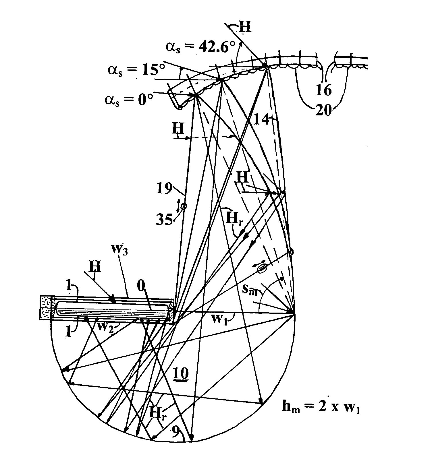
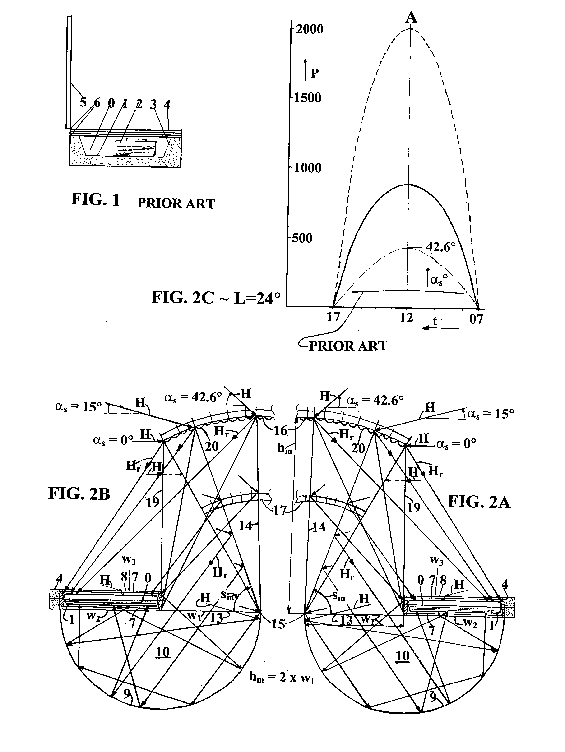
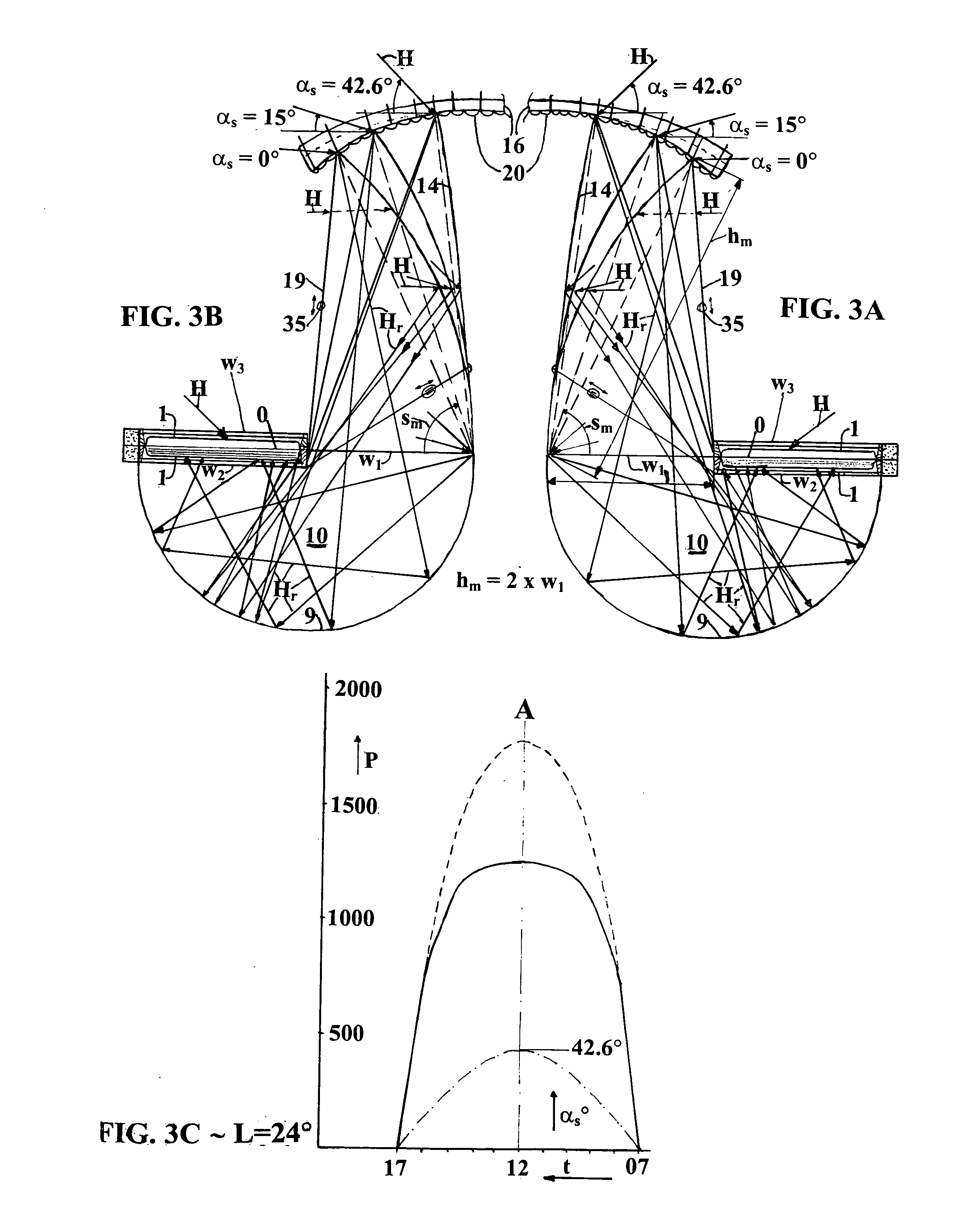
0239] As yet other useful components in the present invention are provided sheets 13 of a material transparent to sunlight. Said transparent sheets 13 are installed in approximately horizontal position under said cooker cavity and sideways from said outer wall of said cooker cavity, closing off the windows casu quo apertures w.sub.1 and w.sub.2 above said concave reflective cavity 9, thereby creating a closed-off, still-air, concave reflective cavity 9, protected from incursion of for example rain, wind, dust, debris, spilled foods and the like. Preferred transparent materials are low-iron glass, having an anti-reflective coating on the surfaces facing the light and / or highly transparent polymers such as, for example, fluoropolymers, acrylics, polyesters, polycarbonates.
0240] First 1 and second 1 heat conducting metal plates are used as lower and upper high temperature light absorbers in food cooking environments. Preferred economical long life materials resistant to corrosion in said environments are ferritic stainless steels, sheet metal, for example types 409, 430 or 434, in the bright annealed surface quality. Said preferred material can have a 0.2% yield strength of 205 MPA at a stagnation temperature of 300 centigrade, said yield strength being higher than the yield strength of conventional more expensive 18% chrome, 8% nickel austenitic stainless steels, such as type 304. Further advantages of said preferred material are a low thermal expansion coefficient of less than sixty percent of said conventional stainless steel and last but not least an excellent heat conductivity of 24 watts per meter centigrade in the temperature range of twenty to two hundred centigrade; that means more than fifty percent better heat conductivity than said conventional austenitic stainless steel. Preferred sheet metal thickness ranges from about one tenth of a millimeter for small portable light duty cookers to about two millimeter for heavy duty professional cookers. Said sheet metal can be easily formed, even in said spectrally selective coated state into said cavity shaped first and second trays by well-known simple deep drawing techniques without intermediate reheating. Said ferritic stainless steel sheet metal is eminently resistant to stress corrosion and more importantly, to pitting types of corrosion caused by halogen ions such as chlorides as may be present in many waters and salted foods. For a 500 watts peak power cooker, convenient for a six person family, a total quantity of about one square meter of said ferritic steel material is required.

Problems solved by technology

The prior art pertaining to PV cells casu quo PV cell modules for electricity generation fails to disclose or suggest a combination of PV cells and a solar cooker for simultaneous casu quo alternating cooking and / or electricity generating operations.
The prior art concentrating type of solar cookers such as for example the parabolic mirror type having the mirror positioned under the cooking vessel has too many drawbacks such as for example cumbersome sun tracking requirements, local hot spots burning the food, glare blinding the cook, sensitivity to wind and food spills fouling said mirror, to be considered for mass cooking.
The cooking performance of hot box solar cookers according to the state-of-the-art is poor, especially so when solar radiation and ambient temperature are low, such as is the case in winter and also in the other seasons during morning hours and late afternoon hours, when the sun is low and the angle of incidence of beam radiation is large.
Even during optimum conditions of solar radiation the temperatures required for frying or baking cannot be sustained.
Poor heat transfer between the absorber and any vessel bottom leads to high temperatures of the non-spectrally selective absorber surface especially so in absorber areas at a distance from the vessel edge, and consequently high heat losses.
State-of-the art solar cooker designs fail to disclose or suggest inexpensive means to obtain higher net to food cooking power casu quo desirable cooking frequencies casu quo warm-keeping of meals on the table or under off-sunshine conditions.
State-of-the art photovoltaic (hereinafter called PV) electricity generation systems of the non-tracking type are characterized by a slow build-up of net electric power delivery, especially so at low and / or unfavorable angles of incidence of sunlight on the PV cells.
State-of-the art cooker designs fail to disclose or suggest any combination of convenient cooking and convenient electricity generating operations in one apparatus wherein PV modules are compelled by the movement of said apparatus to track the sun in a two-axis manner resulting simultaneously in optimum angles of sunlight incidence on said PV cells and said cooker.
State-of-the art solar cooking designs fail to disclose or suggest any method and / or apparatus capable of inducing many people to substitute carbon containing fuels for cooking, by sunlight.

Method used


Image

  • Method and apparatus for achieving worldwide reduction of carbon dioxide emissions and deforestation
  • Method and apparatus for achieving worldwide reduction of carbon dioxide emissions and deforestation
  • Method and apparatus for achieving worldwide reduction of carbon dioxide emissions and deforestation

Examples


working examples

[0279] Several embodiments were tested by the inventor in the Almeria area in Southern Spain in November 2003 for various cooking operations, for example in FIG. 24, a preferred embodiment suitable for windy environments is shown, incorporating two upper guide rails 16 supported by a stabilized upper structure 30 with tie-rods 30 for maintaining optimum mirror guide rail profile 20 position in relation to said mirror hinge line 15 and fine (one degree) tuning of mirror tilt angle, said preferred embodiment as shown in FIG. 24, having three cooking trays with top insulation, bendable mirror surface area 1.35 m.times.0.625 m, first window area 0.45 m.times.0.625 m, trays area three times 0.35 m.times.0.20 m. was tested for cooking foods such as: cooking of brunch consisting of fried eggs, fried bacon and fried tomatoes. In tray 1: fried eggs for three persons, in tray 2: fried bacon for three persons, in tray 3: fried tomatoes for three persons. Said food items were fried in 20 grams ...


PUM


Abstract

Method and apparatus enabling worldwide reduction of carbon dioxide emissions and/or deforestation, personal clean energy system providing for cooking and/or electricity needs, earning emission credits, monetizing values of tradable emission rights/credits accruing from emissions avoided by using the apparatus to pay for the cost of the apparatus and/or to provide ongoing revenue thereby inducing many people to substitute carbon containing fuels for cooking and/or electricity needs by a synergic combination of cooking 0 and electricity generation 21 on sunlight H through a low cost two-axis easy sun tracking mechanism including a bendable mirror 14 having variable curvatures rm and tilt angles sm, optimized for the solar altitudes alphas at the latitudes, seasons and day times from equator to arctic, resulting in greatly augmented cooking power enabling high quality meals 0 through much shorter cooking times and longer/higher PV cell 21 outputs charging batteries 24 powering lights, refrigerator, television, computer, enabling worldwide education and sustainable development.

Description

[0001] Specific reference is made to the provisional application for patent for the present invention filed by this applicant and inventor in the United States Patent and Trademark Office on the fourth of June of the year two thousand and three (Jun. 4, 2003), for which provisional application for patent the United States Patent and Trademark Office has issued application No. 60 / 475,468, confirmation number 9680 and filing receipt barcode number *OC000000010443224*, which was mailed by the United States Patent and Trademark Office to this applicant and inventor on the eighth of July of the year two thousand and three (Jul. 8, 2003). Applicant and inventor therefore claims the benefit under 35 U.S.C. 119 (e) and requests the present non-provisional application to be considered a continuation-in-part of provisional application 60 / 475,468 which is incorporated herein by reference.[0002] Inventor: Romijn, Maarten Martinus[0003] Citizenship: Citizen of the Netherlands[0004] Residence: Nr...

Claims


Application Information

Patent Timeline
Patent Type & Authority Applications(United States)
IPC IPC(8): F24J2/54F24S20/30F24S23/00F24S23/70F24S23/71F24S23/74F24S23/77H02N6/00
CPCF24J2/02F24J2/10H02S99/00Y02B40/18Y02E10/47F24J2/54F24S23/70F24S20/30F24S30/40F24S50/20Y02E10/44Y02E10/50Y02E10/60H02S40/44F24S23/81F24S23/00H02S40/38
Inventor ROMIJN, MAARTEN MARTINUS
Owner ROMIJN MAARTEN MARTINUS
Why Eureka
Try Eureka